


9
Exhaust gas ducting
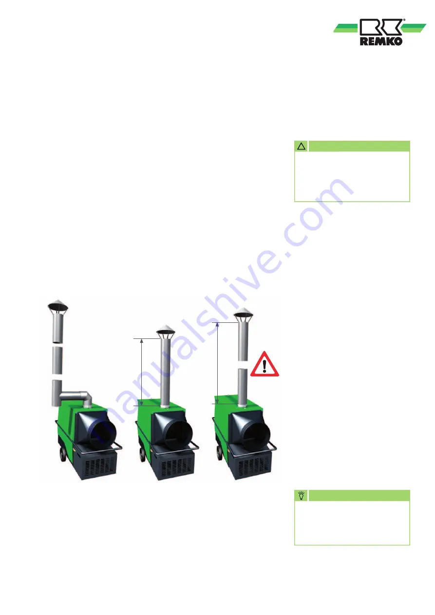
Over 1 metre
Max. 1 metre
In order to avoid the combustion
chamber being damaged due
to condensation of moisture
(condensate) in example 3,
make sure that the exhaust gas
ducting is correctly installed with
a condensate trap as shown in
example 1.
■
Fault-free operation is
guaranteed if the exhaust gas
ducting is fitted in a rising
arrangement and with a vertical
end pipe
■
The exhaust gas routing should
end at least above the height of
the eaves but ideally above the
height of the ridge, in order to
prevent any counter-pressure
being caused by poor weather
conditions (e.g. wind)
■
The minimum distance of 0.6 m
to combustible parts must be
met
■
Exhaust gas ducting parts and
fastening materials are available
as accessories
It is also possible to operate the
units outdoors or in open spaces
without exhaust ducting.
However, we recommend fitting
a 1m exhaust gas duct with a rain
hood on top (example 2), in order
to exclude the ingress of rainwater
and dirt
.
If the units are used for room
heating then the combustion
gases must be routed away, to the
outside if necessary.
■
The exhaust gas ducting must
be designed so that the thermal
lift of the exhaust gases is
guaranteed at all times
■
The exhaust gas ducting must
be designed so that no counter-
pressure can be generated
■
All parts of the exhaust gas
ducting must be reliably
fastened Its diameter must
not be smaller than the outlet
nozzle of the unit
Example 1
Operation with
extended exhaust
gas ducting
Condensate trap
required
Example 2
Operation without
extended exhaust
gas ducting
Max. 1 metre
Example 3
Impermissible
layout
Notes for implementing the 1st.
BImSchV
Units that are not expected to
be operated for longer than
3 months in the same location
are not subject to any approvals
or monitoring as per the
1st. BImSchV.
NOTE
After installing an exhaust
gas system the settings on the
burner should be adapted to
suit the new conditions.
CAUTION
There must be no counter
pressure arising from incorrect
installation of the exhaust
gas ducting under any
circumstances.
!