


13
The general requirements for an isolation transformer
are:
Three phase
3 to 8% impedance
Nonregulated
Sinusoidal output
50/60 Hz, as required
150% overload for 1 minute (max.)
Refer also to Table 2.D for specific information on transĆ
former sizing requirements. In the Transformer" colĆ
umn at the right, maximum kVA and rated kVA figures
are listed in relation to specific dĆc motor hp/ VAC ratĆ
ings.
Reliance Electric offers a number of isolation transformĆ
ers suitable for use with the MinPak Plus controller.
3.5 HP/Current Jumper
- It is necessary to inĆ
spect the Current Scaling/Horsepower Jumper on the
Regulator Module to be sure that it is connected correctĆ
ly for a specific drive motor.
Step 1
- On the drive motor, locate the nameplate. Note
the fullĆload current.
Step 2
- Or, if current is not shown on the nameplate,
refer to Table 3.A. Relate the columns in the table with
known motor data. Read across to the right column
marked Motor Current." This figure indicates the propĆ
er jumper connection to make on the Module where a
corresponding number is etched.
Table 3.A - Horsepower Calibration
230 VAC
HP
Motor Current
Pin Connection
460 VAC
HP
Motor Current
Pin Connection
3
5
7.5
10
13
19
27
36
3
5
7.5
10
15
5.7
10
13
19
27
➀
15
54
20
36
20
72
➀
25
30
40
45
54
72
➀
High HPunits cannot be directly scaled to the lower HPunits, above
line, due to current transformers ratios used in feedback loop
Step 3
- On the Regulator Module, locate the scaling
pins. (Refer to Figure 3.6.) Near them, locate the black
pigĆtail type jumper. Do not move it if it is connected to
the proper pin. If it must be reconnected, carefully lift
connector housing straight up and off the pin. Slide the
connector straight down over the proper pin.
3.6 Regulation Mode Jumper
- The MinPak
Plus controller of drive regulation. The first, which is facĆ
tory shipped, is armature voltage feedback (A).
Optionally, the user may also use tachometer feedback
(T) regulation. In order to use this modes, however, the
Regulation Mode Jumper, one end of which is permaĆ
nently fixed to the Regulator Module, must be moved to
one of two positions. Details of jumper placement are
noted in Section 7, DĆ3969.
DANGER
IF YOU ARE UNSURE WHICH REGULATION
MODE A CONTROLLER SHOULD HAVE, IT IS
IMPORTANT YOU FIND OUT. IF THE JUMPER IS
NOTPROPERLY CONNECTED, PERSONAL INĆ
JURY MAY RESULT.
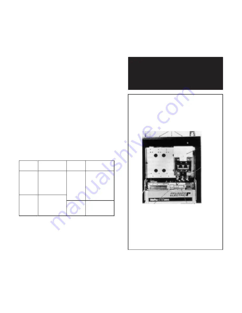
CHASSIS
GROUND
CONDUITKNOCKĆOUTS
TERMINALS
A1-A2
MOTOR
ARMATURE
CIRCUIT
TERMINALS
132, 33, 34, 32
EXTERNAL INTERLOCK
PROTECTIVE CIRCUITRY
(MOTOR THERMOSTAT, ETC.)
THREE PHASE
INCOMING
AĆC LINE
L1, L2, L3
TERMINALS
F1ĆF2
MOTOR SHUNT
FIELD
Figure 3.5 - Three Phase Minpak Plus Wiring
Locations
Summary of Contents for MinPak Plus
Page 1: ......
Page 3: ......
Page 9: ......
Page 13: ......
Page 17: ......
Page 28: ......
Page 29: ......
Page 30: ......
Page 31: ......
Page 32: ...Figure 5 9 230 VAC Auxiliary Panel Assembly Schematics...
Page 33: ...Figure 5 10 460 VAC Auxilliary Panel Assembly Schematics...
Page 34: ......
Page 35: ......
Page 36: ......
Page 37: ......
Page 38: ......
Page 39: ...Figure 5 13B Technical Data 230 VAC Three Phase MinPak Plus...
Page 40: ......
Page 41: ...Figure 5 14B Technical Data 460 VAC Three Phase MinPak Plus...
Page 42: ......
Page 43: ......
Page 44: ......
Page 45: ......
Page 51: ......


