


User Manual RelAir ICS ·03/2019 · VERSION 1.0
9
RelAir ICS
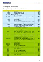
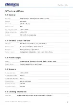
5 Technical Data
5.1 General
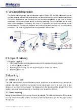
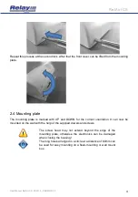
Mounting
Wall mounting or mounting on an in-wall box (60 mm)
Material
ABS, white
W x L x H
(80 x 80 x 25) mm
Protective class
IP40
Operating temperature
-10°C to +55°C
Storage temperature
-20 to +70°C
Humidity
10% to 80% (not condensing)
5.2 Wireless M-Bus Interface
Standard
EN13757-4 and EN13757-3, compatible to OMS
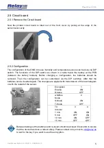
Transmit mode
S1 or T1 (unidirectional) / Frame Format A
Encryption
Mode 0 (not encrypted) or Mode 5
Transmit interval
Configurable by DIP switches: 1 min, 5 min, 10 min, 15 min
5.3 Power Supply
Battery
2 replaceable AA alkaline cells (industrial grade) in scope of supply
Batterie lifetime
Transmit interval 15 min. / up to 10 years
5.4 Sensors
Temperature range
-10°C to +55°C
Temperature accuracy
± 0.3 °C
Temperature resolution
0.1 °C
Humidity range
20% RH to 80% RH
Humidity accuracy
± 2% RH
Humidity resolution
0.1% RH
5.5 Ordering Information
RelAir ICS
Wireless M-Bus Indoor Climate Sensor (Tempe Humidity)


