


PAGE 8
Reimers Electra Steam, Inc. 01/10/2022
HLR 120‐180 Manual ‐ English
REV 1
Piping: This hot water boiler is intended to be used in a
closed pressure system with a circulating hot water pump.
The boiler safety relief valve can have settings from 30 and
up to 150psig. The expansion tank must be sized to meet
the ASME standards for the overall water capacity of your
heating system. The circulating system should also include
an air trap and bleed, as well as automatic water fill. The
water inlet and outlet are located on top of the boiler as
shown in FIGURE 2.
Recommended heating loop piping size, depending on the
boiler heating power:
HLR210 – HLR300: 3" NPS
HLR330 – HLR510: 4" NPS
Install stop valves as close as possible to the boiler supply
and return ports (FIGURE 2).
In order to ensure long term troublefree boiler operation,
we recommend that the water used as boiler feed water to
be tested for hardness. If the water in your area is harder
than 1grain (17mg/L), use a water softener. The main
cause for premature heating element failure in electric
steam boilers is water hardness. If severe corrosion during
inspection of the pressure vessel as indicated in chapter
3.4 of this manual becomes evident, additional tests of
your boiler feed water must be performed. A water analysis
should be performed by a qualified and recognized water
treatment company located in your area.
Recommended levels for boiler feed water:
Recommended levels for boiler water (water inside
pressure vessel when boiler is operating)
The safety valve is designed to discharge hot steam when
the set pressure is exceeded. Ensure that the discharge
port is pointing toward the back of the unit away from the
operator and any aisles. If it is required that discharge
piping be installed from the safety valve, the pipe should
not be smaller than the valve outlet and should be rigidly
supported so as not to place weight on the valve itself.
Important: No valve in this line!
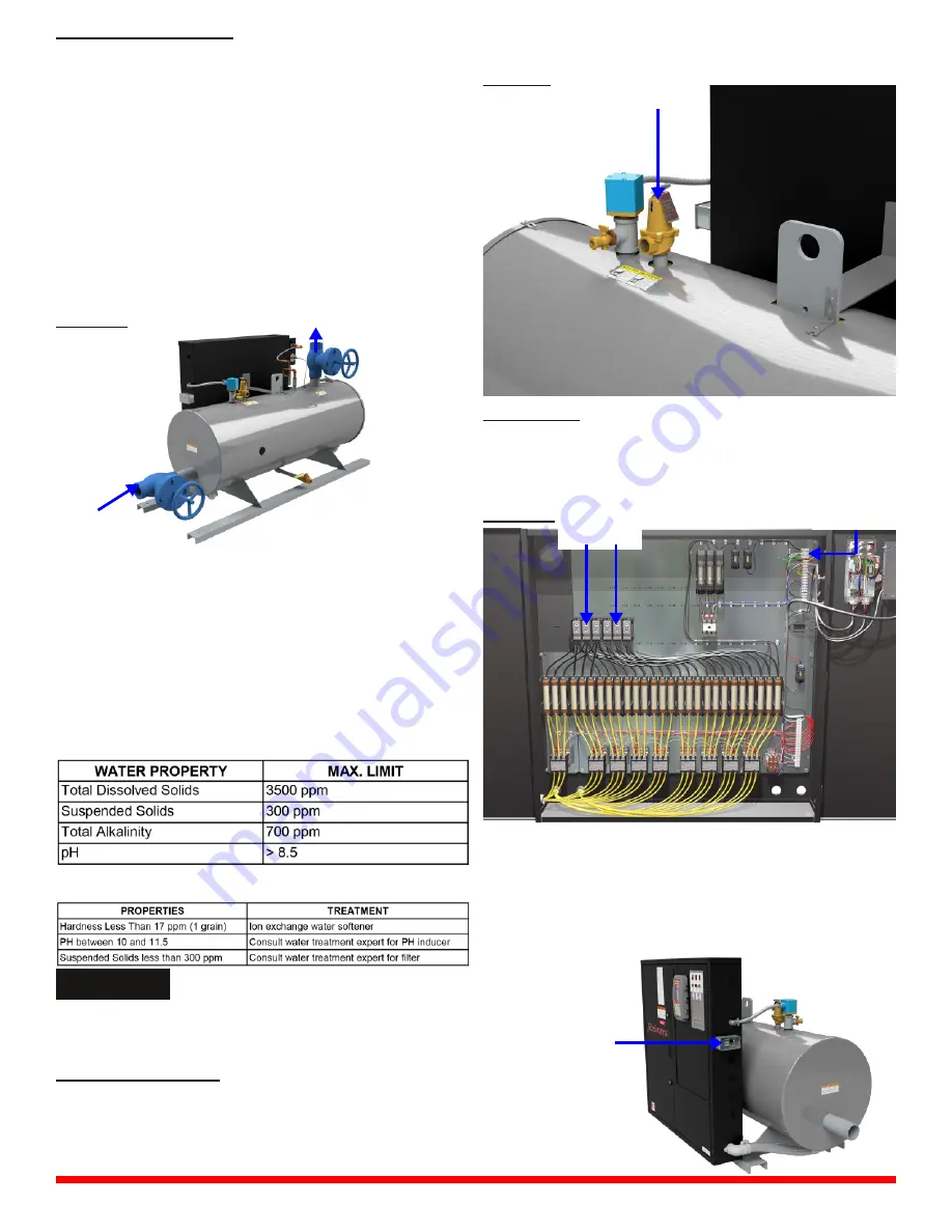
Install a fused disconnect switch near the boiler. It should
be fused as marked on the boiler name plate. Connect the
power supply from the disconnect switch to the terminals in
the boiler control panel. A copy of the wiring diagram is in
the control panel.
Important: Electrical connections to the boiler control panel
(FIG. 3) should be made by a qualified Electrician. All
wiring must comply with local electrical codes.
All boiler models that are equipped with a transformer
option (OPT1010 or OPT1011) do not require a separate
external control voltage power supply.
NOTICE
Do not add any chemicals to
the boiler feed water unless
specifically recommended by a
qualified and recognized water
treatment company.
1.2 Heating Loop Piping
1.3 Safety Relief Valve
1.4 Electrical
Safety Valve
FIGURE 2
Return Line
Supply Line
FIGURE 2
Main Power
FIGURE 3
Control
Voltage
ROOM/PROCESS
THERMOSTAT
CONNECTION


