Valid from 07.2009
* Des solutions polymères à l’infini
www.rehau.com
Construction
Automotive
Industry
rautool G1/H/G1
bedienunGsanleitunG / operatinG instructions / mode d’emploi /istruzioni per l’uso 856690 de/en/Fr/it
Page 1: ...from 07 2009 Des solutions polymères à l infini www rehau com Construction Automotive Industry rautool G1 H G1 bedienungsanleitung operating instructions mode d emploi istruzioni per l uso 856690 DE EN FR IT ...
Page 2: ...2 Bedienungsanleitung 3 Operating instructions 21 Mode d emploi 39 Istruzioni per l uso 57 RAUTOOL G1 H G1 Inhalt Contents indice sommaire ...
Page 3: ...Bau Automotive Industrie rautool G1 H G1 bedienungsanleitung 856690 DE Gültig ab 07 2009 Technische Änderungen vorbehalten www rehau com ...
Page 4: ...reibung und Funktionsprinzip 9 Technische Daten Hydraulikaggregat 10 Gerätebeschreibung und Funktionsprinzip Hydraulikaggregat 10 Werkzeugvorbereitung 11 Montageablauf 12 Wichtige Hinweise 14 Wichtige Hinweise RAUTITAN 15 Wartungshinweise 16 Hinweise zur Behebung von Funktionsstörungen 18 Garantiekarte Kopiervorlage bitte ausfüllen 73 ...
Page 5: ...at nicht für andere Zwecke oder Dimensionen 8 Betreiben Sie das Gerät nur mit REHAU Originalteilen und Zube hör 9 Lassen Sie Wartungs und Reparaturarbeiten nur in einer von REHAU autorisierten Fachwerkstatt ausführen Für Arbeiten von Fremdpersonal wird von uns jegliche Haftung abgewiesen Die Adressen der autorisierten Servicecenter erfahren Sie von Ihrem Händler oder REHAU Verkaufsbüro Werkzeugspe...
Page 6: ...Maximaldruck anlaufen lassen REHAU übernimmt keine Haftung für Schäden oder Verlet zungen die auf unsicheren Gebrauch des Produktes man gelhafte Instandhaltung oder unsachgemäße Produkt und Systemanwendung zurückzuführen sind Zur Planung und Montage verwenden Sie bitte unsere gültige Technische Information Den jeweils aktuellen Stand der Unter lage erhalten Sie von Ihrem zuständigen Fachgroßhandel...
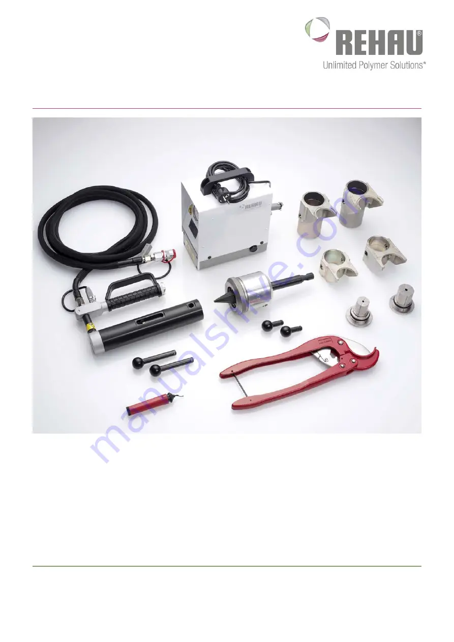
Page 7: ...ydraulikaggregat HMP 1 bzw Fußpumpe G1 Aufweitdorn mit Haltemutter incl 2 kurzen Steckstiften 2 lange Steckstifte Aufweitkopf 50 x 6 9 bzw 50 x 4 6 Aufweitkopf 63 x 8 6 bzw 63 x 5 7 Satz Verpressjoche G1 50 Satz Verpressjoche G1 63 Rohrschere 63 Entgrater Transportkoffer G1 Bedienungsanleitung ...
Page 8: ...1 75 x 8 6 Art Nr 137584 Aufweitkopf G1 90 x 8 2 Art Nr 137604 Aufweitkopf G1 110 x 10 Art Nr 137614 Fußpumpe G1 HFP 14 22 Art Nr 138132 Satz Verpressjoche G1 40 Art Nr 201802 Satz Verpressjoche G1 50 Art Nr 137624 Satz Verpressjoche G1 63 Art Nr 137634 Satz Verpressjoche G1 75 Art Nr 137644 Satz Verpressjoche G1 90 Art Nr 137654 Satz Verpressjoche G1 110 Art Nr 137664 Hydraulikaggregat HMP 1 Art ...
Page 9: ...r G1 Arbeitseinheiten zur Aufnahme der Jochsätze bzw Aufweiteinsatz G1 5 Jochsatz G1 Ein Satz besteht aus einem kurzen und langen Joch 5a Langes Joch Bewegliches Joch 5b Kurzes Joch Feststehendes Joch 6 Steckstifte G1 Befestigungsvorrichtung des Jochsatzes bzw Aufweiteinsatzes auf dem Presszylinder 7 Aufweitkopf 50 Aufweitwerkzeug zum Aufweiten der Rohre 50 8 Aufweitkopf 63 Aufweitwerkzeug zum Auf...
Page 10: ...er Jochsätze bzw Aufweiteinsatz G1 3 Jochsatz G1 Ein Satz besteht aus einem kurzen und langen Joch 3a Langes Joch Bewegliches Joch 3b Kurzes Joch Feststehendes Joch 4 Steckstifte G1 Befestigungsvorrichtung des Jochsatzes bzw Aufweiteinsatzes auf dem Presszylinder 5 Aufweitkopf 50 Aufweitwerkzeug zum Aufweiten der Rohre 50 6 Aufweitkopf 63 Aufweitwerkzeug zum Aufweiten der Rohre 63 7 Aufweiteinsatz...
Page 11: ...mutter entfernen Aufweit köpfe plan auflegen Haltemutter vollständig aufschrauben Ab der Dimension 75 mm werden die Aufweitköpfe direkt ohne Haltemutter aufgeschraubt Aufweitköpfe 75 mm eben falls vollständig aufschrauben Vermeiden Sie mögliche Verkan tungen beim Aufschrauben Der Werkzeugzylinder wird zum Aufweiten und Verpressen verwendet Der Umbau ist hierfür wie folgt durchzuführen Verpressen Z...
Page 12: ...hiebehülsen aus Metall muss die innere Anfasung zur Verbindung zeigen 3 Rohr zweimal um 30 versetzt aufweiten Schiebehülse darf sich nicht in der Aufweitzone befinden Aufweitung mittels Druckschalters bzw Betätigung des Fußhebels vornehmen RAUTOOL G1 H G1 MONTAGEABLAUF 4 Fitting in das Rohr bis zum Anschlag stecken Nach kurzer Zeit sitzt der Fitting im Rohr fest Memory Effekt Achtung Alle Dichtrip...
Page 13: ...tzt werden Eine Verarbeitung bei Temperaturen unter 10 C und über 45 C kann zu Schäden an den Verbindungskomponenten am Werkzeug und oder zu Personenschäden führen Minimale Verarbeitungstemperatur von 10 C nicht unter schreiten Bei niedrigen Temperaturen unterhalb 0 C wird empfohlen die Verbindungskomponenten vor der Verarbeitung in einer wärmeren Umgebung vorzulagern Bitte beachten Sie ferner den...
Page 14: ...rd Ersatz liefert Ihnen Ihr Händler oder REHAU Verkaufsbüro Aufweitwerkzeug grundsätzlich immer bis zum Anschlag in das Rohr einstecken RAUTOOL G1 H G1 wichtige Hinweise Achtung Fassen Sie nicht in die beweg lichen Teile Quetschgefahr Auf korrekte Lage des Fitting im Werkzeug achten Durch Anset zen der Werkzeuge am falschen Fittingbund wird die Verbindung überpresst ...
Page 15: ... circumstances A éviter impérativement Da evitare assolutamente Evitar siempre NEU NEW NOUVEAU NUOVO NUEVO НОВЫЙ ø 40 ø 40 201802 001 ALT OLD ANCIEN VECCHIO ANTIGUO ø 40 ø 40 137964 001 201802 001 137964 001 RAUTOOL G1 H G1 Wichtige hinweise RAUTITAN ø 40 ø 40 ...
Page 16: ...bnutzung Beschädigte Werkzeuge dürfen nicht mehr verwendet werden und sind sofort zur Reparatur an ein autorisiertes Service Center zu senden Vergewissern Sie sich ob beim Verpressen die Jochsätze vollstän dig schließen und die Schiebehülse bis zum Fittingkragen aufge schoben ist Kegel des Aufweiteinsatzes regelmäßig einfetten Kein Fett auf die Oberfläche der Aufweitsegmente auftragen Falls übersc...
Page 17: ...hrmals betätigen ohne Druck aufzubauen Korrekter Ölstand ist Mitte Schau glas wenn Pumpenaggre gat steht Zum Entlüften Fußpumpe hoch stellen und Verpresswerkzeug tieferlegen Werkzeug mehrmals betätigen ohne Druck aufzubau en oder auf der Seite liegt Öleinfüllschraube obenliegend Füllen Sie auf keinen Fall zu viel Öl nach Werkzeug vor Lagerung reinigen und trocknen ...
Page 18: ...gegebenenfalls Öl nachfüllen Prüfen des Hydraulikschlauches auf Leckage Drucklos evtl auswechseln lassen Gerät entlüften Gerät kommt nicht auf 450 bar Druck Ölstand überprüfen gegebenenfalls Öl nachfüllen Prüfen des Hydraulikschlauches auf Leckage Drucklos evtl auswechseln lassen Gerät entlüften Falls die Funktionsstörung nicht behebbar ist Gerät an REHAU Servicecenter oder Ihren Händler senden RA...
Page 19: ...19 ...
Page 20: ...20 ...
Page 21: ...Construction Automotive Industry rautool G1 H G1 operating instructions 856690 EN Valid from 07 2009 Subject to technical modifications www rehau com ...
Page 22: ...Equipment description and operating principle 27 Technical Data Hydraulic unit 28 Device description and functional principle of the hydraulic unit 28 Tool preparation 29 Assembly procedure 30 Important notes 32 Important notes RAUTITAN 33 Maintenance notes 34 Notes on trouble shooting 36 Guarantee card Kindly fill out copying sheet 75 ...
Page 23: ...purposes or dimensions 8 Only operate the tool with original REHAU parts and accessories 9 Only have servicing and repair work done at a specialist work shop authorised by REHAU We reject any liability for work perfomed by non authorised person nel The addresses of authorised service centers may be obtained from your dealer or REHAU sales office Tool specific safety warnings electro hydraulic unit...
Page 24: ...or from over heating do not operate at maximum pressure for any prolonged period REHAU will not accept any liability for damage or injury attri butable to unsafe product use poor maintenance or improper product or system usage For planning and assembly kindly use our current Technical Information brochure You can obtain the up to date brochure from your wholesale dealer your REHAU sales office or ...
Page 25: ...draulic unit HMP 1 and or foot pump G1 expander set with fixing nut incl 2 short pins 2 long pins expander head 50 x 6 9 and or 50 x 4 6 expander head 63 x 8 6 and or 63 x 5 7 set of clamping jaws G1 50 set of clamping jaws G1 63 pipe cutter 63 deburrer transport case G1 operating instructions ...
Page 26: ...x 8 6 art no 137584 expander head G1 90 x 8 2 art no 137604 expander head G1 110 x 10 art no 137614 Foot pump G1 HFP 14 22 art no 138132 set of clamping jaws G1 40 art no 201802 set of clamping jaws G1 50 art no 137624 set of clamping jaws G1 63 art no 137634 set of clamping jaws G1 75 art no 137644 set of clamping jaws G1 90 art no 137654 set of clamping jaws G1 110 art no 137664 Hydraulic unit H...
Page 27: ...r to return the tool to the start position 4 Compression cylinder G1 Work units to hold the jaw sets expander set G1 5 Jaw set G1 A set comprises one short and one long jaw 5a Long jaw Moving jaw 5b Short jaw Fixed jaw 6 Pins G1 Device for fixing the jaw set expander set on the compression cylinder 7 Expander head 50 Expanding tool for expanding pipes 50 8 Expander head 63 Expanding tool for expan...
Page 28: ... Compression cylinder G1 Work units to hold the jaw sets expander set G1 3 Jaw set G1 A set comprises one short and one long jaw 3a Long jaw Moving jaw 3b Short jaw Fixed jaw 4 Pins G1 Device for fixing the jaw set expander set on the compression cylinder 5 Expander head 50 Expanding tool for expanding pipes 50 6 Expander head 63 Expanding tool for expanding pipes 63 7 Expander set G1 Expander dev...
Page 29: ...ing nut position expander head correctly screw fixing nut completely on From di mension 75 mm expander heads are screw ed on directly without fixing nut Expander heads 75 mm must also be screwed on com pletely Avoid possible cants when mounting The tool cylinder is used for expanding and clamping The tool conversation is for this as follows Clamping The expander set must be remo ved for clamping T...
Page 30: ... must point towards the joint 3 Expand pipe rotate 30 and repeat The compression sleeve must not be in the expansion area Expansion is to be carried out using the pressure switch or by activating the foot lever RAUTOOL G1 H G1 Assembly procedure 4 Insert fitting into pipe up to the stop After a brief period the fitting will sit tightly in the pipe memory effect Caution All sealing ribs must be cov...
Page 31: ... and at right angles Processing at temperatures of under 10 C and over 45 C may result in damage to the joint components the tool and or in personal injury Do not work below the minimum processing temperature of 10 C At low temperatures below 0 C it is recommended that the joint components be stored in a warm environment before processing Please observe also the instruction leaflet of the compress...
Page 32: ...is will damage the pipe Replacements are available form your dealer or from the REHAU sales office Always insert expanding tool into pipe up to the stop RAUTOOL G1 H G1 Important notes Caution Do not touch moving parts risk of trapping fingers Make sure fitting is correctly seated in tool Applying the tool to the wrong fitting collar will over compress the joint ...
Page 33: ...o circumstances A éviter impérativement Da evitare assolutamente Evitar siempre NEU NEW NOUVEAU NUOVO NUEVO НОВЫЙ ø 40 ø 40 201802 001 ALT OLD ANCIEN VECCHIO ANTIGUO ø 40 ø 40 137964 001 201802 001 137964 001 RAUTOOL G1 H G1 Important notes RAUTITAN ø 40 ø 40 ...
Page 34: ...e or visible wear Damaged tools may no longer be used and are to be sent immedi ately for repair to an authorised Service Center Make sure that the jaw sets fully close when compressing and that the compression sleeve is inserted fully up to the fitting collar Regularly grease the expander set tapers Do not apply any grease to the expander segments If excess grease gets onto the expander segments ...
Page 35: ...ithout building up pressure The correct oil level is to the middle of the display glass when pump unit is standing upright To vent the system stand foot pump upright and lower down clamp ing tool operate tool several times without building up pressure or on its side oil filler screw facing upwards Do not overfill with oil Clean and dry tool before storing it away ...
Page 36: ...Check oil level if necessary top up Check hydraulic hose for leakage not under pressure and have it replaced if necessary Vent system Unit not reaching 450 bar pressure Check oil level if necessary top up Check hydraulic hose for leakage not under pressure and have it replaced if necessary Vent system If the faults cannot be remedied return tool to REHAU Service Center or to your dealer RAUTOOL G1...
Page 37: ...37 ...
Page 38: ...38 ...
Page 39: ...Bâtiment Automobile Industrie rautool G1 H G1 mode d emploi 856690 FR Valable à partir de 07 2009 Sous réserve de modifications techniques Des solution polymères à l infini www rehau com ...
Page 40: ... de fonctionnement 45 Données techniques groupe hydraulique 46 Description du groupe hydraulique et principe de fonctionnement 46 Préparation de l outillage 47 Montage 48 Conseils importants 50 Conseils importants RAUTITAN 51 Conseils d entretien 52 Conseils concernant l élimination des défauts de fonctionnement 54 Certifcat de garantie veuillez remplir le formulaire 75 ...
Page 41: ...u l appareil hydroélectrique à d autres fins ou pour d autres dimensions 8 Utilisez l outillage uniquement avec les pièces d origine et accessoires REHAU 9 Ne faites réaliser les travaux d entretien et de réparation que dans un centre de service agréé par REHAU Nous n assumons aucune responsabilité pour des travaux qui n ont pas été réalisés par des personnes agréées Votre revendeur ou votre agenc...
Page 42: ...sponsabilité pour les dommages ou blessures résultant d une utilisation non sécurisée du produit d un défaut d entretien ou d une utilisation impropre du produit et du système Veuillez utiliser pour la planification et le montage notre infor mation technique valable Vous pouvez vous procurer la dernière version de cette documentation auprès de votre grossiste compétent de votre agence commerciale ...
Page 43: ...aulique groupe hydraulique HMP 1 et ou pompe à pied G1 insert à expandre avec écrous et 2 goupilles courtes 2 goupilles longues tête à expandre 50 x 6 9 ou 50 x 4 6 tête à expandre 63 x 8 6 ou 63 x 5 7 jeu de mors G1 50 jeu de mors G1 63 coupe tube 63 couteau à ébavurer coffret G1 mode d emploi ...
Page 44: ...34 Tête d expansion G1 75 x 8 6 no d art 137584 Tête d expansion G1 90 x 8 2 no d art 137604 Tête d expansion G1 110 x 10 no d art 137614 Pompe à pied G1 HFP 14 22 no d art 138132 Jeu de mors G1 40 no d art 201802 Jeu de mors G1 50 no d art 137624 Jeu de mors G1 63 no d art 137634 Jeu de mors G1 75 no d art 137644 Jeu de mors G1 90 no d art 137654 Jeu de mors G1 110 no d art 137664 Groupe hydrauli...
Page 45: ...Cylindres de compression G1 Support recevant les jeux de mors ou le support de tête d expansion G1 5 Jeu de mors G1 Un jeu est composé d un mors court et d un mors long 5a Mors long Mors mobile 5b Mors court Mors fixe 6 Goupilles G1 Système de fixation du jeu de mors ou de l insert d expansion sur le cylindre de compression 7 Tête d expansion 50 Outil d expansion des tubes de diamètre 50 8 Tête d ...
Page 46: ...u le support de tête d expansion G1 3 Jeu de mors G1 Un jeu est composé d un mors court et d un mors long 3a Mors long Mors mobile 3b Mors court Mors fixe 4 Goupilles G1 Système de fixation du jeu de mors ou de l insert d expansion sur le cylindre de compression 5 Tête d expansion 50 Outil d expansion des tubes de diamètre 50 6 Tête d expansion 63 Outil d expansion des tubes de diamètre 63 7 Inser...
Page 47: ...ées Pour changer la tête d expansion enlever l écrou placer correcte ment la tête revisser l écrou A par tir de la dimension 75 mm les têtes d ex pansion sont fixées directement sans écrou de ser rage Soit l écrou soit la tête d expansion doivent être vissés jusqu au bout Le cylindre est utilisé pour l expansion et le sertissage La transformation de l outillage s effectue pour cela de la manière s...
Page 48: ...doit être tourné vers la pince à expandre 3 Expandre le tube à deux reprises en le tournant de 30 La bague à sertir ne doit pas se trouver dans la zone d expansion Mettre en œuvre l expansion par l intermédiare de l interrupteur ou en action nant le levier avec le pied RAUTOOL G1 H G1 Montage 4 Enfiler le raccord sur l extrémité du tube Après rétraction effet mémoire le raccord est solidement fixé...
Page 49: ...d un raccordement à une température inférieure à 10 C ou supérieure à 45 C peut entraîner un endommagement des constituants de la connexion de l outil ou peut entraîner des risques de blessures corporelles Ne pas effectuer de raccordements à des températures inférieures à 10 C A de faibles températures inférieures à 0 C il est conseillé d entreposer les constituants de la connexion par ex tubes ra...
Page 50: ...votre revendeur ou votre Agence Commerciale REHAU pour le remplacement Toujours insérer l expanseur dans le tube jusqu à la butée RAUTOOL G1 H G1 CONSEILS IMPORTANTS Attention Ne posez pas la main sur les pièces mobiles risque de pince ment Veiller au positionnement correct du raccord dans l outillage Le fait d actionner l outillage à partir d un mau vais emplacement du raccord entraîne la surcomp...
Page 51: ...circumstances A éviter impérativement Da evitare assolutamente Evitar siempre NEU NEW NOUVEAU NUOVO NUEVO НОВЫЙ ø 40 ø 40 201802 001 ALT OLD ANCIEN VECCHIO ANTIGUO ø 40 ø 40 137964 001 201802 001 137964 001 RAUTOOL G1 H G1 CONSEILS IMPORTANTS RAUTITAN ø 40 ø 40 ...
Page 52: ...s être utilisés et doivent être envoyés immédiatement à un centre de service agréé pour être réparés Assurez vous lors du sertissage que les mors sont appliqués com plètement sur toute leur surface de pression et à angle droit et que la bague à sertir est complètement insérée jusqu en butée de raccord Lubrifier régulièrement les cônes des expanseurs Ne pas appli quer de lubrifiant sur la surface d...
Page 53: ...le est correct lorsqu il atteint la moitié du verre indicateur à la position verticale Pour purger le circuit hydrau lique placer la pompe en hauteur et l outillage à sertir plus bas Actionner plusieurs fois la pompe sans créer de pression et ramener l outillage à l aide du levier purgeur Recom men cer le processus le cas échéant ou latérale vis de remplissage d huile supérieure Ne mettez pas trop...
Page 54: ... Vérifier le tuyau hydraulique en recherchant une fuite absence de pression le faire éventuellement remplacer Purger l appareil L appareil n atteint pas la pression de 450 bars Vérifier le niveau d huile en rajouter éventuellement Vérifier le tuyau hydraulique en recherchant une fuite absence de pression le faire éventuellement remplacer Purger l appareil S il ne peut être remédié à l incident de ...
Page 55: ...55 ...
Page 56: ...56 ...
Page 57: ...Edilizia Automotive Industria rautool G1 H G1 istruzioni per l uso 856690 IT Valido a partire di 07 2009 Salvo modifiche tecniche www rehau com ...
Page 58: ...cipio di funzionamento 63 Dati tecnici gruppo idraulico 64 Preparazione dell attrezzo e principio di funzionamento del gruppo idraulico 64 Preparazione dell attrezzo 65 Istruzioni di montaggio 66 Indicazioni importanti 68 Indicazioni importanti RAUTITAN 69 Istruzioni di manutenzione 70 Istruzioni utili per eliminare eventuali anomalie 71 Garanzia compilare il modulo 75 ...
Page 59: ...ttroidraulico per qualsia si altro scopo o dimensione 8 Utilizzare l apparecchio soltanto con accessori e pezzi originali REHAU 9 Affidare gli interventi di manutenzione e riparazione esclusivamente ad un officina specializ zata autorizzata REHAU Decliniamo ogni responsabilità in caso di lavori eseguiti da personale esterno alla nostra azienda Gli indirizzi dei centri di assistenza tecnica autoriz...
Page 60: ...mento troppo prolungato intorno alla pressione massima a causa di un eventuale surriscaldamento del motorino La REHAU declina ogni responsa bilità in caso di danni o feri menti dovuti ad un uso improprio del prodotto manutenzione insufficiente o applicazioni improprie del prodotto o del sistema Per la progettazione e il montaggio fare sempre riferimento all Informazione Tecnica vigente La versione...
Page 61: ...e idraulico Gruppo idraulico HMP 1 WE Mandrino allargatubi con dadodi fermo incl 2 spine di innesto corte 2 spine di innesto lunghe Espansore 50 x 6 9 Espansore 63 x 8 6 Set gioghi pressori G1 50 Set gioghi pressori G1 63 Cesoia tagliatubi 63 Sbavatore Contenitore a valigetta Istruzioni per l uso ...
Page 62: ...t 137584 Espansore G1 90 x 8 2 Cod art 137604 Espansore G1 110 x 10 Cod art 137614 Pompa a pedale G1 HFP 14 22 Cod art 138132 Set gioghi pressori G1 40 Cod art 201802 Set gioghi pressori G1 50 Cod art 137624 Set gioghi pressori G1 63 Cod art 137634 Set gioghi pressori G1 75 Cod art 137644 Set gioghi pressori G1 90 Cod art 137654 Set gioghi pressori G1 110 Cod art 137664 Gruppo idraulico HMP 1 Cod ...
Page 63: ... trovano posto i set di teste a forcella o gli espansori idraulici G1 5 Set di teste a forcella G1 un set consiste di una testa a forcella breve e una lunga 5a Testa a forcella lunga testa a forcella mobile 5b Testa a forcella corta testa a forcella fissa 6 Spinotti ad innesto G1 dispositivo di fissaggio della testa a forcella o dell espansore idraulico sul cilindro di compressione 7 Espansore 50 ...
Page 64: ...G1 3 Set di teste di compressione G1 un set consiste di una testa di compressione breve e una lunga 3a Testa di com pressione testa di compressione mobile 3b Testa di com pressione corta testa di compressione fissa 4 Perni ad inne sto G1 dispositivo di fissaggio della testa di compressione o dell espansore idraulico sul cilindro di compressione 5 Espansore 50 attrezzo per l espansione dei tubi 50 ...
Page 65: ... espansori to gliere il dado di fermo sistemare gli espansori in piano quindi riavvitare con la massima cautela il dado di fermo Gli espansori di dimensione superiore a 75 mm vengono avvitati direttamente vale a dire senza dado di fermo Il cilindro dell attrezzo serve sia per scampanare che per comprimere operando le dovute trasformazioni illustrate qui di seguito Compressione per la compressione ...
Page 66: ...occanti in metallo la bisellatura interna deve essere rivolta verso il collegamento 3 Allargamento mediante pinza espansore Allargare il tubo per due volte ruotandolo di 30 Badare alla distanza minima lunghezza del manicotto scorrevole tra l espansore e il manicotto autobloccante RAUTOOL G1 H G1 ISTRUZIONI DI MONTAGGIO 4 Inserire il raccordo fino all ar resto Dopo poco tempo si realizza una salda ...
Page 67: ...uper ficie Una lavorazione a temperature inferiori a 10 C e superiori a 45 C può provocare danni alle componenti del collegamento all attrezzo e o ferite alle persone La temperatura di lavorazione minima non deve essere inferiore a 10 C In caso di basse temperature inferiori a 0 C si consiglia di immagazzinare i componenti del collegamento in un ambiente caldo prima della lavorazione Seguire atten...
Page 68: ...rovvede ranno immediatamente alla sostitu zione Innestare l allargatore nel tubo fino all arresto RAUTOOL G1 H G1 INDICAZIONI IMPORTANTI Attenzione Evitare il contatto diretto con le parti mobili pericolo di contu sioni Accertare che il raccordo all interno dell utensile sia posizionato cor ret tamente Appli cando l uten sile sull elemento di giunzione del rac cordo errato il collegamento viene co...
Page 69: ...ircumstances A éviter impérativement Da evitare assolutamente Evitar siempre NEU NEW NOUVEAU NUOVO NUEVO НОВЫЙ ø 40 ø 40 201802 001 ALT OLD ANCIEN VECCHIO ANTIGUO ø 40 ø 40 137964 001 201802 001 137964 001 RAUTOOL G1 H G1 INDICAZIONI IMPORTANTI RAUTITAN ø 40 ø 40 ...
Page 70: ...lico per escludere l assenza di danni o di usura visibile Assicurarsi durante la compressione che le teste di compressione si chiudano completamente e che il manicotto autobloccante sia spinto fino al collare del raccordo Ingrassare regolarmente il mandrino conico dell attrezzo per espansione Non applicare grasso sulla superficie dei segmenti delle teste di espansione Se il grasso in eccesso finis...
Page 71: ...ile di compressione La quanitità d olio è corretta se il livello di riempiento dell olio risulta al centro del tubo di livello quando il complesso è in posizio ne verticale Per eseguire le operazioni di sfia to posizionare la pompa a pedale in alto e abbassare l utensile di compressione o in appoggio sul fianco vite di riempimento olio in alto Evitare assolutamente di rabboccare con troppo olio La...
Page 72: ...lare senza corrente il cavo di alimentazione provvedendo alla relativa sostituzione qualora dovesse presentare eventuali perdite Sfiatare l apparecchio L apparechio non raggiunge la pressione die 450 bar Controllare il livello dell olio provvedendo all occorrenza ad un rabbocco Controllare senza corrente il cavo di alimentazione provvedendo alla relativa sostituzione qualora dovesse presentare eve...
Page 73: ...73 ...
Page 74: ...74 ...
Page 75: ...m these tests They do not however in any way detract from the quality of the tool The tools have been tested and approved by our quality control department If despite the careful manufacture and assembly of the tool you still have reason for complaint we kindly ask you to return the tool for repair or exchange together with this guarantee card Any further claims regardless of their type are not va...
Page 76: ...stanbul Tel 90 212 35547 00 istanbul rehau com UA Dnepropetrowsk Tel 380 56 3705028 dnepropetrowsk rehau com Kiew Tel 380 44 4677710 kiev rehau com Lviv Tel 380 32 2244810 lviv rehau com Odessa Tel 380 48 7800708 odessa rehau com US Chicago Tel 1 630 3173500 chicago rehau com Detroit Tel 1 248 8489100 detroit rehau com Grand Rapids Tel 1 616 2856867 grandrapids rehau com Greensboro Tel 1 336 85220...