Regin product information
Regin product information
3
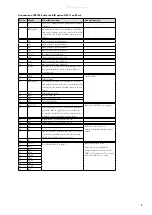
Connection of EP7408 with the EIB option X9017 on Port 3.
Pin no Signal
Detailed function
Group function
1
+C
+24 V DC. Output for analog inputs AI and digital
inputs DI.
2
EMI ground
This terminal is connected internally to the PIFA’s
frame and to internal protective circuits. It should be
connected to the ground rail with a separate, heavy
gauge.
3
AI1
Analog input 1, type Multisensor
4
AI2
Analog input 2, type Multisensor
5
AI3
Analog input 3, type Multisensor
6
AI4
Analog input 4, type Multisensor
7
AGnd
Reference pole for AI1-AI4
8
SCR
Connection for screen, AI1-AI4
9
AO1
Analog output 1, type Standard
10
AO2
Analog output 2, type Standard
11
AGnd
Reference pole for AO1-AO2 for high-ohm loads.
For low-ohm loads, use the 0 V terminal (20) as
reference pole.
12
DTR
Option X9017
13
Gnd
Signal Ground
14
EMI ground
This terminal is connected internally to the PIFA’s
frame and to internal protective circuits. It should be
connected to the ground rail with a separate, heavy
gauge.
15
TxD
Transmit Data (Out)
16
RxD
Receive Data (In)
17
RTS
Request To Send (Out)
18
CTS
Clear To Send (In)
19
+24 V DC
Inputs for +24 V DC power supply
20
0 V
Power supply 0 V. The 0 V-connection is normally
grounded at the supply source, so as to define the
potential to earth reference and to compensate for
disturbances and transients from I/O signals.
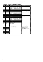
21
DI1
Digital input 1, type Standard 24 V DC
22
DI2
Digital input 2, type Standard 24 V DC
23
B3
EXOline connection, Port 3
Galvanically insulated from all other
circuits.
24
A3
25
N3
The 0 V reference. This should be connected to the
screen of the communication cable, which in turn
should be grounded at one point at least.
26
E3
27
TxD3
See “The RS232 Port” on page 2.
RS232 connection, Port 3
This connection is galvanically
insulated from the internal circuits.
GND3 is the signal zero. Use screened
cable and earth it at one point.
28
RxD3
29
RTS3
30
CTS3
31
GND3
32
SEL3
33
DTR3
34
DSR3
35
DCD3
36
RI3


