background image

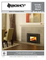
Regency CI1200 / CI1250 Wood Cast Insert

5

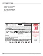
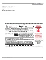
SAFETY LABEL

This is a copy of the label that accompanies each 


CI1250 Wood Insert

. We have printed a copy 

of the contents here for your review.

NOTE: 

 Regency units are constantly being 

improved.  Check the label on the unit and if 
there is a difference, the label on the unit is 
the correct one.

LISTED FACTORY BUILT FIREPLACE INSERT
CERTIFIED FOR USE IN CANADA AND U.S.A.
MODEL: 

CI1250

TESTED TO:
ULC S628-M93  / UL 1482-2006 / ULC S627-00  


WN #  16600

DO NOT REMOVE THIS LABEL

367

COMPONENTS REQUIRED FOR INSTALLATION: 5.5" (140mm) OR 6"     (152MM) STAINLESS STEEL LINER. STANDARD ADAPTOR (171-932) OR OFFSET 
ADAPTOR (171-936).  STANDARD COMPONENT:  FAN ELECTRICAL RATING: VOLTS 115, 60HZ.
DO NOT REMOVE BRICKS OR MORTAR IN MASONRY FIREPLACE.  FOR USE WITH SOLID WOOD FUEL ONLY.  DO NOT USE GRATE OR ELEVATE FIRE.  
BUILD WOOD FIRE DIRECTLY ON HEARTH.  OPERATE WITH FEED DOOR CLOSED, OPEN TO FEED FIRE ONLY.  REPLACE GLASS ONLY WITH CERAM-
IC GLASS (5MM).  INSPECT AND CLEAN CHIMNEY FREQUENTLY.   UNDER CERTAIN CONDITIONS OF USE CREOSOTE BUILDUP MAY OCCUR RAPIDLY.  
DO NOT OVERFIRE, IF INSERT GLOWS YOU ARE OVER-FIRING.

MINIMUM CLEARANCES TO COMBUSTIBLE MATERIALS  (MEASURED FROM INSERT BODY)

918-916

MANUFACTURED BY:

FPI FIREPLACE PRODUCTS INTERNATIONAL LTD.

6988 VENTURE ST.

DELTA,  BC    V4G 1H4

HOT WHILE IN OPERATION 

DO NOT TOUCH.  KEEP CHILDREN, 

CLOTHING AND FURNITURE AWAY.  

CONTACT MAY CAUSE SKIN BURNS.   

READ ABOVE INSTRUCTIONS.

ADJACENT SIDEWALL  A)  15in / 380mm
MANTLE 

B)  20in / 510mm

TOP FACING 

C  14in / 355 mm

SIDE FACING 

D)  7.375in / 185mm

INSTALL AND USE ONLY IN ACCORDANCE WITH THE MANUFACTURER'S INSTALLATION AND OPERATING INSTRUCTIONS.  INSTALL AND USE ONLY
IN MASONRY FIREPLACE OR FACTORY BUILT FIREPLACE.
CONTACT LOCAL BUILDING OR FIRE OFFICIALS ABOUT RESTRICTIONS AND INSTALLATION INSPECTION IN YOUR AREA.

UNITED STATES ENVIRONMENTAL  PROTECTION  
AGENCY CERTIFIED TO COMPLY WITH JULY 1990, 
PARTICULATE EMISSION STANDARDS.


 JAN 

 FEB 

 MAR  APR 

MAY 

JUN 

JUL 

AUG 

SEPT  OCT 

NOV   DEC

2010

2011

2012

(Duplicate
Serial #)

MADE IN CANADA

367

DATE OF

MANUFACTURE

INSTALLER ET UTILISER SELONS LES INSTRUCTIONS DU FABRICANT.  INSTALLER ET UTILISER DANS UN FOYER DE MACONNERIE OU PRÉFAB-
RIQUÉ.  APPELER VOTRE INSPECTEUR DE BÂTIMENT OU LE DÉPARTMENT D’INCENDIE LOCAL POUR LES CODES LOCAUX ET POUR INSPECTÉE 
VOTRE INSTALLATION ET FOYER.

CAUTION

ATTENTION:

CHAUD LORS DE FONCTIONNEMENT.

NE PAS TOUCHER. GARDEZ LES EN-

FANTS, VÊTEMENTS ET MEUBLES AU 

LOIN. 

UN CONTACT AVEC LE PEAU PEUT OC-

CASIONER DES BRULURES.BRÛLURES 

CUTANÉES.

LIRE CETTE ÉTIQUETTE.

PIÈCES NÉCESSAIRES POUR INSTALLATION :5.5" (140MM) OR 6" (152MM) CONDUITS EN ACIER INOXYDABLE. ADAPTATEUR DE CONDUIT DE 
FUMÉE STANDARD (171-932) OU COUDÉ (171-936) COMPONENT STANDARD : FAN ELECTRICAL RATING: VOLTS 115, 60HZ.
N'ENLEVER NI BRIQUES NI MORTIER DU FOYER LORSQUE VOUS EFFECTUEZ L'INSTALLATION DU POÊLE ENCASTRABLE. UTILISER SEULEMENT 
DU BOIS DE CHAUFFAGE.  NE PAS UTILISER UNE GRILLE, ÉTABLIR LE FEU DIRECTEMENT SUR LES BRIQUES DANS LE FOND DU POÊLE. OPÉREZ 
AVEC LA PORTE DE NOURRITURE FERMÉE, OUVERTE POUR NOURRIR LE FEU SEULEMENT.  REMPLACEZ LE VERRE SEULEMENT AVEC LE VERRE 
CÉRAMIQUE (5 MM).  INSPECTEZ ET NETTOYEZ VOTRE CHEMINÉE FRÉQUEMMENT.  LA FRÉQUENCE D’UTILISATION ET LA TEMPÉRATURE AUX-
QUELS LE POÊLE EST UTILISÉ DE FAÇON RÉGULIÈRE PEUT AFFECTER CETTE ACCUMULATION DE CRÉOSOTE.  NE PAS SURCHAUFFER. 

INSTALL ONLY ON A NON-COMBUSTIBLE HEARTH RAISED (F) 1.5IN / 38MM 
ABOVE AN ADJACENT COMBUSTIBLE FLOOR.  COMBUSTIBLE FLOOR MUST 
BE PROTECTED BY NON-COMBUSTIBLE MATERIAL EXTENDING 
(E) 16 IN / 405MM (US), 18 IN / 457MM (CAN) TO  FRONT AND (G)  8 IN / 205MM 
TO SIDES FROM FUEL DOOR.

INSTALLER SUR UN ÂTRE DE MATÉRIAU NOM COMBUSTIBLE SURÉLEVÉ
(F) 1,5 POUCES / 38MM-DESSUS DU PLANCHER COMBUSTIBLE ADJACENT. 
LE PLANCHER COMBUSTIBLE DOIT ÊTRE PROTÉGÉ PAR LE MATÉRIAU NOM 
COMBUSTIBLE QUI ÉTENDRE
(E) 16 IN / 405MM (ETATS-UNIS), 18 IN / 457 MM (CAN) EN AVANT ET  (G)  8 IN / 
205MM LES CÔTÉ DE LA PORTE.

Summary of Contents for Alterra CI1200

Page 1: ...C Canada V4G 1H4 918 893a CI1200 CI1250 Alterra Wood Inserts 01 19 11 Owner s Installation Manual Tested by Installer Please complete the details on the back cover and leave this manual with the homeowner Homeowner Please keep these instructions for future reference ...

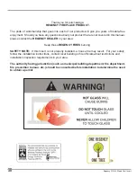
Page 2: ... REGENCY DEALER in your area Keep those REGENCY FIRES burning SAFETY NOTE If this Insert is not properly installed a house fire may result For your safety follow the installation instructions contact local building or fire officials about restrictions and installation inspection requirements in your area The authority having jurisdiction such as municipal building department fire department fire p...

Page 3: ...alling Your Insert 11 Installation Into a Masonry Fireplace 13 Installation Into a Factory Built Fireplace 13 Stainless steel smoke deflector Installation 14 Cast faceplate installation 15 3 piece backing plate installation 18 Door reversal 19 Brick Flue Baffle Secondary Air Tube Installation 20 Firebrick Assembly 20 Draft Control 20 First Fire 21 Fan Operation CS1250 Only 22 Cord reversal 22 Ash ...

Page 4: ...ES CUTANÉES LIRE CETTE ÉTIQUETTE CAUTION ATTENTION ADJACENT SIDEWALL A 15in 380mm MANTLE B 20in 510mm TOP FACING C 14in 355 mm SIDE FACING D 7 375in 185mm INSTALL AND USE ONLY IN ACCORDANCE WITH THE MANUFACTURER S INSTALLATION AND OPERATING INSTRUCTIONS INSTALL AND USE ONLY IN MASONRY FIREPLACE OR FACTORY BUILT FIREPLACE CONTACT LOCAL BUILDING OR FIRE OFFICIALS ABOUT RESTRICTIONS AND INSTALLATION ...

Page 5: ...TION AGENCY CERTIFIED TO COMPLY WITH JULY 1990 PARTICULATE EMISSION STANDARDS JAN FEB MAR APR MAY JUN JUL AUG SEPT OCT NOV DEC 2010 2011 2012 Duplicate Serial MADE IN CANADA 367 DATE OF MANUFACTURE INSTALLER ET UTILISER SELONS LES INSTRUCTIONS DU FABRICANT INSTALLER ET UTILISER DANS UN FOYER DE MACONNERIE OU PRÉFAB RIQUÉ APPELER VOTRE INSPECTEUR DE BÂTIMENT OU LE DÉPARTMENT D INCENDIE LOCAL POUR L...

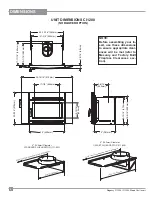
Page 6: ... 498mm 9 9 16 15 381mm 18 13 16 478mm 17 11 16 449mm 22 9 16 574mm 244mm 21 3 8 543mm 15 1 16 383mm 9 15 16 250mm NOTE Before assembling your In sert use these dimensions to ensure appropriate clear ances will be met refer to Masonry and Factory Built Fireplace Clearances sec tion DIMENSIONS 6 152mm Diameter OFFSET FLUE ADAPTOR 171 936 14 1 8 from flue centerline to rear of faceplate 16 15 16 430m...

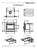
Page 7: ... 22 13 16 579mm 250mm NOTE Before assembling your In sert use these dimensions to ensure appropriate clear ances will be met refer to Masonry and Factory Built Fireplace Clearances sec tion UNIT DIMENSIONS CI1250 WITH STANDARD BLOWER 6 152mm Diameter STANDARD FLUE ADAPTOR 171 932 6 152mm Diameter OFFSET FLUE ADAPTOR 171 936 14 1 8 from flue centerline to rear of faceplate 16 15 16 430mm ...

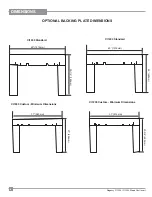
Page 8: ...t Insert DIMENSIONS OPTIONAL BACKING PLATE DIMENSIONS 40 1016mm 40 1016mm 37 940mm 37 914mm 29 1 2 749mm 27 686mm 26 660mm 23 5 8 600mm CI1250 Standard CI1250 Custom Minimum Dimensions CI1200 Custom Minimum Dimensions CI1200 Standard ...

Page 9: ...ower 1 Read all instructions before installing and us ing your fireplace insert Install and use only in accordance with manufacturer s installation and operating instructions 2 Check your local building codes Building Inspection Department You may require a permit before installing your insert Be aware that local codes and regulations may override some items in the manual WARNING Careless installa...

Page 10: ... C 1 25 therefore Rbrick 1 C 1 1 25 0 80 1 8 mineralboardofk 0 29 therefore Rmin bd 1 0 29 x 0 125 0 431 Total R Rbrick Rmineral board 0 8 0 431 1 231 Step c CompareproposedsystemRof1 231tospeci fied R of 0 893 Since proposed system R is greaterthanrequired thesystemisacceptable DEFINITIONS Thermal Conductance C Btu W hr ft2 o F m2 K Thermal Conductivity k Btu inch W Btu hr ft3 o F m K hr ft o F T...

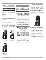
Page 11: ...equired height Secure adaptor using 3 screws 1 in the front and 1 each on the left and right side Flex Liner Diagram 1 Yourinsertisveryheavyandwillrequiretwoorthreepeopletomove it into position Whenhandlingcastparts pleasehandlewithcareastheycanbedamaged 1 Open door to a 45 angle 2 Holding door firmly from top and bottom lift door up and off to remove 3 Lift the unit up onto the Hearth and slide i...

Page 12: ...flue adaptor as shown in diagram 4 While sliding the unit into place pull on the rod to ensure that the flue adaptor is properly engaged See diagram 5 Pull Rod 10 Ensure that the unit is still level 11 To complete the installation and to ensure a secure fit and connection of the flue adaptor to the insert it is essential that the two bolts flat wash ers and lock washers supplied with packaged manu...

Page 13: ...lledaspertherequirements of your local inspection authority Three methods of flue connection are acceptable in most areas these include 1 Positiveflueconnection wherealargeblocking plate and a short connector pipe is used 2 Directflueconnection whereasmallerblocking plate and a connector pipe to the first flue liner tile is used 3 Full flue liner where a stainless steel rigid or flexible liner pip...

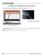
Page 14: ... 2 hand tightened bolts To replace the deflector loosen off both bolts and slide defector upward and out Install new defector and hand tighten bolts Ensure positive location of the defector prior to hand tightening WARNING Operation of the unit with out proper installation of smoke deflector will void warranty Smoke deflector is installed through the door opening in location shown in diagram Smoke...

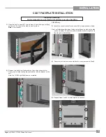
Page 15: ...n below Line up the left side casting bracket with the left side bracket on the unit Note the CI1200 right left sides are reversible 4 Secure the left cast surround with the two bolts removed in Step 2 5 Repeat Steps 2 and 4 to install right cast surround CI1250 Only 3 Install fan controls into left surround with 2 screws as shown below Note Left side faceplate when facing unit will have a notch o...

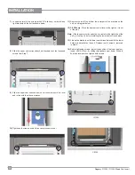
Page 16: ...ntrol lever to the right so it is out of the way Note If the fan power cord needs to be re routed to the right side of the unit go to step 16 before installing the lower cast surround piece 13 Line up the brackets on the lower cast surround piece with the lower holes in the bracket on the unit Replace two 2 screws removed in step 9 14 Before tightening screws adjust the position of the lower cast ...

Page 17: ...t side of the unit if necessary Before installing the lower cast surround run the cord between the left cast surround and the unit Then run the cord along the lower part of the lower cast surround and out in between the right cast and the unit 17 With the cord re routed follow steps 13 15 to complete the installa tion ...

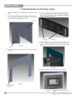
Page 18: ...he CI1250 2 The pointed end of the screws should be facing the front of the back ing plate 3 Install 2 clips to the back of the top cast faceplate with hex bolts If the unit is already installed remove the top cast faceplate from the unit if access is too difficult see Cast Faceplate Installation in the owners manual for instructions 4 Slide the backing plate over the clips on the back of the cast...

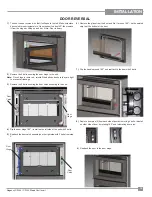
Page 19: ...eakage 3 Remove the 2 bolts securing the door catch assembly to the unit 6 Remove the glass from the door and flip it around 180 so the painted strip is at the bottom of the door 7 Flip the handle around 180 and reattach to the door with 2 botls 4 Flip the door hinge 180 install on the left side of the unit with 2 bolts 5 Reattach the door catch assembly on the right side with 2 bolts from step 3 ...

Page 20: ...to place with a hammer A tighter fit will ensure the tube will not move when the unit is burning 2 Slide the left baffle brick over the front air tube and then slide it back over the rear air tube 3 Tilt the left baffle brick up on top of the side channel and it will leave enough room to posi tion the right baffle brick in the same manner as Step 1 above Then reposition the left baffle brick flat ...

Page 21: ...left open to provide adequate ventilation while this tempo rary condition exists Burning the insert at a very high temperature the first few times may damage the paint Burn fires at a moderate level the first few days 8 Do not place anything on the insert top during the curing process This may result in damage to your paint finish 9 Duringthefirstfewhoursitmaybemoredifficult to start the fire As y...

Page 22: ...r Low for fan speed The automatic temperature sensor will engage the blower when the unit is at temperature and will shut off the blower once the fire has gone out and the unit has cooled to below a useful heat output range To manually operate the fan system push the first switch to Man and second switch to either high or Low This will bypass the sensing device and allow full control of the fan Sw...

Page 23: ... a noncombustible floor or on the ground well away from all combustible materials pending final disposal If the ashes are disposed of by burial in soil or otherwise locally dispersed theyshouldberetainedintheclosedcontaineruntil all cinders have thoroughly cooled Other waste should not be placed in the ash container SOME SAFETY GUIDELINES 1 Neverusegasoline gasolinetypelanternfuels kerosene charco...

Page 24: ... care fully swing open and check the clearance to the Right Hand Cast Side Iftightorrubbing loosenthe 7 16nutsandadjusttheclearance and then re tighten GLASS REPLACEMENT Allow the stove to cool before removing or replacing glass Remove the door from the stove and remove the glass retainer Use caution when removing broken glass to avoid injury When placing the replacement glass in the door make sur...

Page 25: ...fires Removal of the spacer washer shown in the diagram below will allow the catch to be moved closer to the door frame causing a tighter seal Remove and replace the nuts washer and spacer as shown TO REMOVE THE FAN 1 See next page Maintenance The sealed bearings are lubricated there is no need to lubricate them further Extra lubricant will cause more lint and dust buildup causing the bearings to ...

Page 26: ...ve two 2 screws with 3 16 Allen Key to remove lower cast sur round set aside on a soft surface 4 Lift fan housing up off pins on floor of unit 5 Remove fan from unit 9 To install fan reverse Steps 8 1 6 Remove 3 screws to remove fan heat shield 7 Slide back the protect sheath on the wiring disconnect the black red and white wires 8 Disconnect the ground wire located on the left side of the fan hou...

Page 27: ...area of the door on a cold stove close the door Try to remove the paper by pulling The paper should not pull out easily if it does try adjusting the door latch if that doesn t solve the problem replace the door gasket Inspect condition and seal of Glass Gasket Door Gasket Perform paper test replace gasket if required Check and lubricate door hinge latch Use only high temperature anti seize lube ie...

Page 28: ...ws set of 2 6 Screws 10 24 x 3 8 9 156 514 Door Handle Assembly 11 156 513 Door Catch 12 156 201 Door Assembly Metallic Black no glass 846 570 Med Density Door Gasket Kit 13 156 241 Cast Handle 14 074 954 Air Tube 1 Qty 1 15 033 953 Air Tube 3 4 Qty 1 16 073 955 Baffle 2 set 17 171 932 Standard Flue Adaptor 171 936 Offset Flue Adaptor 18 156 060N Draft plate arm 19 820 483 Stainless smoke deflecto...

Page 29: ...Door Catch 12 156 201 Door Assembly Metallic Black no glass 846 570 Med Density Door Gasket Kit 13 156 241 Cast Handle 14 074 954 Air Tube 1 Qty 1 15 033 953 Air Tube 3 4 Qty 1 16 073 955 Baffle 2 set 17 171 932 Standard Flue Adaptor 171 936 Offset Flue Adaptor 918 893 Manual Not available as a replacement part 1 2 12 19 5 11 18 20 13 9 18 910 140 3 way switch 19 910 157 P Fan Assembly 20 156 060N...

Page 30: ... Bottom Surround Not available as a replacement part FIREBRICK Part Description 156 960 Complete Brick Set 1 Brick Regular Full Size 1 1 4 x 4 1 2 x 9 2 Brick Partial 1 1 4 x 2 x 9 3 Brick Partial 1 1 4 x 1 1 4 x 9 4 Brick Partial 1 1 4 x 4 1 2 x 8 5 Brick Partial 1 1 4 x 4 1 4 x 8 6 Brick Partial 1 1 4 x 4 1 2 x 4 1 2 Not available as a replacement part CI1250 Bottom Surround CI1200 Bottom Surrou...

Page 31: ... or costs of workmanship from unauthorized service persons or dealers At all times FPI reserves the right to inspect product in the field which is claimed to be defective All claims must be submitted to FPI by authorized selling dealers It is essential that all submitted claims provide all of the necessary information including customer name purchase date serial type of unit problem and part or pa...

Page 32: ...________________________________________________________ Phone ___________________________________________________________ Date Installed ______________________________________________________ Serial No __________________________________________________________ Register your Regency warranty online www regency fire com Reasons to register your product online today View and modify a list of all you...

Reviews: