background image


Regency CI1150 Wood Cast Insert

  |     

7

installation

6.  Alteration  of  the  fireplace  in  any  manner  is 

not permitted with the following exceptions;  

  a.  

external trim pieces which do not affect the op

-

eration of the fireplace may be removed pro

-

viding they can be stored on or within the fire

-

place for re-assembly if the insert is removed. 


 b.

 the chimney damper may be removed to 

install the chimney liner.

7.  Circulating  air  chambers  (i.e.  in  a  steel  fire

-

place liner or metal heat circulator) shall not 

be blocked.

8.  Means must be provided for removal of the 

insert to clean the chimney flue.

9.  Inserts that project in front of the fireplace must 

be supplied with appropriate supporting means.

10. Installer must mechanically attach the supplied 

label to the inside of the firebox of the fireplace 

into which the insert is installed.

Fireplace Specifications

Your  fireplace  opening  requires  the  following 

minimum sizes:

Height:  

23" (584 mm)  


Width: 

25" (635 mm)

Depth:

(w/ standard flue adaptor) 

15-1/8" (384 mm)

(w/ offset flue adaptor)


18-1/8" (460 mm) 

Chimney Specifications

Before installing, check and clean your chimney 

system thoroughly. If in doubt about its condition, 

seek professional advice. Your Regency Insert is 

designed for installation into a masonry fireplace 

that is constructed in accordance with the require-

ments of "The Standard for Chimneys, Fireplaces, 

Vents, and Solid Fuel Burning Appliance", N.F.P.A. 

211, the National Building Code of Canada, or the 

applicable local code requirements.  

The appliance, when installed, must be electrically 

grounded in accordance with local codes or, in the 

absence of local codes, with the National Electrical 

Code, ANSI/NFPA 70, or the Canadian Electrical 

code, CSA C22.1.

Regency Inserts are designed to use either a 5.5" 

(140mm) or 6" (152mm) flue.

This insert must be connected to a code-approved 

masonry chimney or listed factory-built fireplace 

chimney with a direct flue connector into the first 

chimney liner section.  The chimney size should 

not be less than or more than three times greater 

than the cross-sectional area of the flue collar.

Requirements for Installing 
Solid-fuel Inserts in Factory-built 
Fireplaces.

1.  The insert must be tested and meet the require-

ments  of  UL  1482  (U.S.)  and  or  ULC  S628 

(Canada) when tested in a masonry fireplace 

built per ULC S628.

2.  The factory-built fireplace must be listed per 

UL 127 or ULC S610.

3.  Clearances  obtained  from  the  masonry  fire

-

place tests are also relevant for installation in 

factory-built fireplaces.

4.  Installation  must  include  a  full  height  listed 

chimney  liner  type  HT  requirements  (2100 

degree F.) per UL 1777 (U.S.) or ULC S635 

(Canada). The liner must be securely attached 

to the insert flue collar and the chimney top.

5.  Means must be provided to prevent room air 

passage to the chimney cavity of the fireplace. 

This may be accomplished by sealing the 

damper area around the chimney liner, or 

sealing the fireplace front.

Regency Inserts are constructed with the highest 

quality materials and assembled under strict quality 

control procedures that ensure years of trouble free 

and reliable performance.

It is important that you read this manual thoroughly 

and fully understand the installation and operating 

procedures.  Failure to follow instructions may result 

in property damage, bodily injury or even death. The 

more you understand the way your Regency Insert 

operates, the more enjoyment you will experience 

from knowing that your unit is operating at peak 

performance.

Before Installing Your Insert

1.  Read all instructions before installing and us-

ing your fireplace insert.  Install and use only 

in accordance with manufacturer’s installation 

and operating instructions.

2.  Check your local building codes - Building In-

spection Department.  You may require a 

permit 

before installing your insert. Be aware that 

local codes and regulations may override 

some items in the manual.


WARNING:  Careless installation is the ma-

jor cause of safety hazard.  Check all local 

building and safety codes before installation 

of unit.

3.  Notify your home insurance company that you 

plan to install a fireplace insert.

4.  Your fireplace insert is heavy and requires two 

or more people to move it safely.  The insert and 

surrounding structure can be badly damaged 

by mishandling.

5.  If  your  existing  fireplace  damper  control  will 

become inaccessible once you have installed 

your Regency Insert, you should either remove 

or secure it in the open position.

6.  Inspect  your  fireplace  and  chimney  prior  to 

installing your insert to determine that it is free 

from cracks, loose mortar or other signs of 

damage. If repairs are required, they should 

be completed before installing your insert.  Do 

not remove bricks or mortar from your masonry 

fireplace.

7.  Do  not  connect  the  insert  to  a  chimney  flue 

servicing another appliance or an air distribution 

duct.

"

WARNING

: This fireplace has been converted 

for use with a wood insert only and cannot be 

used for burning wood or solid fuels unless 

all original parts have been replaced, and the 

fireplace re-approved by the authority having 

jurisdiction."

Important: 

T

he blower to this appliance must be turned 

off  anytime  the  fuel  door  is  opened.  Prior  to 

turning the blower back on, ensure there are no 

embers near the blower which may have fallen 

onto the hearth when the fuel door was opened. 

Once the fuel door is closed, the blower may 

be turned back on.

Summary of Contents for Alterra CI1150

Page 1: ...a V4G 1H4 920 160 CI1150 Alterra Wood Insert 01 15 20 Owner s Installation Manual Tested by Installer Please complete the details on the back cover and leave this manual with the homeowner Homeowner Please keep these instructions for future reference Project No 0219WN027S ...

Page 2: ...thin the building envelope It is against federal regulation to operate this wood heater in a manner inconsistent with operating instructions in this manual This heater is designed to burn natural wood only Higher efficiencies and lower emissions generally result when burning air dried seasoned hardwoods as compared to softwoods or to green or freshly cut hardwoods DO NOT BURN Treated wood Lawn cli...

Page 3: ... 17 Stainless Steel Smoke Deflector Installation 18 Operating Instructions Seasoned Wood 19 Operating Instructions 20 Draft Control 20 First Fire 20 Fan Operation 21 Cord reversal 21 Maintenance Ash Disposal 22 Safety Guidelines and Warnings 22 Maintenance 23 Creosote 23 Wood Storage 23 Door Gasket 24 Glass Cleaning 24 Door Removal 24 Glass Replacement 24 Handle Replacement 25 Door Catch Adjustmen...

Page 4: ...UR LATÉRAL ADJACENT PIÈCES OBLIGATOIRES POUR L INSTALLATION GAINE DE CHEMINÉE HOMOLOGUÉE EN ACIER INOXYDABLE DE 5 5 PO 140mm ou 6 PO 152mm PIÈCE EN OPTION VENTILATEUR PIÈCE NO 172 917 CARACTÉRISTIQUES ÉLECTRIQUES 115 VOLTS 60 HZ 0 6 AMPS DANGER RISQUE D ÉLECTROCUTION DÉBRANCHER LE COURANT AVANT DE PROCÉDER À L EN TRETIEN DE L APPAREIL NE PAS RETIRER LES BRIQUES OU LE MORTIER DU FOYER EN MAÇONNERIE...

Page 5: ... of faceplate 6 152mm Diameter STANDARD FLUE ADAPTOR 172 942 17 5 16 440mm 14 1 8 from flue centerline to rear of faceplate 6 152mm Diameter OFFSET FLUE ADAPTOR 172 946 NOTE Beforeassembling your Insert use these dimensions to ensure ap propriate clearances will be met refer to Masonry and Factory Built Fire placeClearancessection Offset Flue Adapter Standard Flue Adapter 15 1 8 384 mm 15 1 8 384 ...

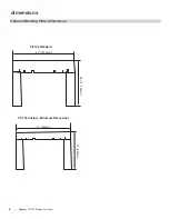
Page 6: ...gency CI1150 Wood Cast Insert dimensions Optional Backing Plate Dimensions 40 1016mm 40 1016mm 37 940mm 37 914mm 29 1 2 749mm 27 686mm 26 660mm 23 5 8 600mm CI1150 Standard CI1150 Custom Minimum Dimensions ...

Page 7: ... F per UL 1777 U S or ULC S635 Canada The liner must be securely attached to the insert flue collar and the chimney top 5 Means must be provided to prevent room air passage to the chimney cavity of the fireplace This may be accomplished by sealing the damper area around the chimney liner or sealing the fireplace front Regency Inserts are constructed with the highest qualitymaterialsandassembledund...

Page 8: ...at your floor protection and hearth will meet the standards for clearance to combustibles Your hearth extension must be made from a non combustible material Extending 16 for US and 18 for Canada measured from the fuel loading door Unit CI1150 Adjacent Side Wall to side A Mantel to top B Top Facing to top C Side Facing to side D Minimum Hearth Extension E Minimum Hearth Side Extension F From Top of...

Page 9: ...Diagram 2 Alignment of the flue adaptor can be critical during the install it is recommended that the flex liner be left as compressed as possible Before inserting the unit the adaptor should hang when level slightly above the required height 3 Install the unit by first setting the rear of the unit into the fireplace See Diagram 3 En sure that the unit is centered in the existing fireplace and lin...

Page 10: ...pproximately the alignment of the flue liner with the position of the smoke outlet hole on the insert to check for possible offset If an offset is required use the appropriate offset adaptor in your installation 6 Oncetheaboveitemshavebeenchecked slide your insert into position after first positioning and securing the flue liner to the offset adaptor Attachtherodtotheadaptorandslidetheadap tor ont...

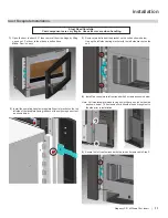
Page 11: ...wn below Line up the left side casting bracket with the left side bracket on the unit 5 Secure the left cast surround with the two bolts removed in Step 3 4 Install fan controls into left surround with 2 screws as shown below Note Left side faceplate when facing unit will have a notch on the side as shown below The extension cord should also be brought out to the side prior to installation 2 Insta...

Page 12: ...ight so it is out of the way Note If the fan power cord needs to be re routed to the right side of the unit go to step 16 before installing the lower cast surround piece 13 Line up the brackets on the lower cast surround piece with the lower holes in the bracket on the unit Replace the two 2 bolts removed in step 11 14 Before tightening the bolts adjust the position of the lower cast sur round unt...

Page 13: ... the right side of the unit if necessary Before installing the lower cast surround run the cord between the left cast surround and the unit Then run the cord along the lower part of the lower cast surround and out in between the right cast and the unit 17 With the cord re routed follow steps 13 15 to complete the installa tion ...

Page 14: ...OG EH IDFLQJ WKH IURQW RI WKH EDFN LQJ SODWH Install 2 clips to the back of the top cast faceplate with hex bolts If the unit is already installed remove the top cast faceplate from the unit if access is too difficult see Cast Faceplate Installation in the owners manual for instructions 6OLGH WKH EDFNLQJ SODWH RYHU WKH FOLSV RQ WKH EDFN RI WKH FDVW WRS 7KHUH DUH QRWFKHV LQ WKH EDFNLQJ SODWH ZKHUH ...

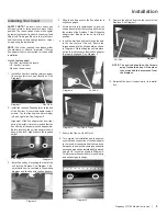
Page 15: ...age 3 Remove the 2 bolts securing the door catch assembly to the unit 6 Remove the glass from the door and flip it around 180 so the painted strip is at the bottom of the door 7 Flip the handle around 180 and reattach to the door with 2 bolts 4 Flip the door hinge 180 install on the left side of the unit with 2 bolts 5 Reattach the door catch assembly on the right side with 2 bolts from step 3 Doo...

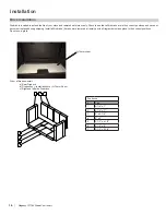
Page 16: ...positions Do not use a grate LyTherm sheet Order of firebrick install a Rear Firebrick b Firebox floor install brick over LyTherm Sheet c Right and left side Firebricks Fire bricks Size 1 4 1 4 x 7 2 4 1 2 x 7 3 9 x 4 1 2 4 9 x 2 5 3 1 2 x 4 1 2 6 4 1 4 x 8 7 3 1 2 x 2 1 4 1 4 6 5 3 7 2 ITEM NO PART NUMBER QTY DESCRIPTION 7 RD 14287 2 3 500 x2 2500 BRICK 6 RD 14286 2 4 250 x 8 000 x 30 DEG BRICK 5...

Page 17: ...easier to remove the air tubes by removing both the bottom right base brick and right side wall brick 5 Install left and right baffle brackets installation of left baffle bracket shown below Baffle Installation 4 Install the right and left side baffles right side baffle shown below 3 Install the center baffle 6 Secure the baffles into position by lifting up on the brick slightly so that the lockin...

Page 18: ...en off both bolts and slide deflector downward push deflector to the back wall of the unit and manoeuver out Install new deflector and hand tighten bolts Ensure positive location of the deflector prior to hand tightening WARNING Operation of the unit with out proper installation of smoke deflector will void warranty Smoke deflector installed with 2 bolts Note This is a cutaway view from the back o...

Page 19: ...es Softer woods like pine spruce and poplar aspen that is cut split and stacked properly in the early spring maybe be ready for burning in the fall Extremely hard woods like oak and maple and large pieces of firewood may take a minimum of a full year to dry enough Drying may also take longer in damp climates There are a few ways to tell if wood is dry enough to burn efficiently Use as many indicat...

Page 20: ...rate level and avoid a large fire Only after 5 or 6 such fires can you operate the stove at its maximum setting and only after the metal has been warmed Always build up the fire slowly 4 For the first few days the stove will give off an odour from the paint This is to be expected as thehightemperaturepaintbecomesseasoned Windows and or doors should be left open to provide adequate ventilation whil...

Page 21: ...position pushed in The fully closed posi tion is the low burn setting The fan must not be turned on until a fire has been burning for at least 30 minutes Also note it is recommended that the fan be turned off before each fuel loading and again wait for 30 minutes before the fan is turned on again This is to allow the stove to reach its optimum temperature To operate fan automatically push switch o...

Page 22: ...e draft control Over firing can cause extensive damage to your stove including warping and premature steel corrosion Over firing will void your warranty 6 Do not permit creosote or soot build up in the chimney system Check and clean chimney at regular intervals Failure to do so can result in a serious chimney fire 7 YourRegencystovecanbeveryhot Youmaybe seriously burned if you touch the stove whil...

Page 23: ...apours which might otherwise be deposited within the system 3 Only burn seasoned wood Avoid burning kiln dried wet or green wood Seasoned wood has been dried at least one year Wood Storage Store wood under cover such as in a shed or cov ered with a tarp plastic tar paper sheets of scrap plywood etc asuncoveredwoodcanabsorbwater from rain or snow delaying the seasoning process Maintenance It is ver...

Page 24: ...nd check the clearance to the Right Hand Cast Side Iftightorrubbing loosenthe 7 16nutsandadjusttheclearance and then re tighten Glass Replacement Allow the stove to cool before removing or replacing glass Remove the door from the stove and remove the glass retainer Use caution when removing broken glass to avoid injury When placing the replacement glass in the door make sure that the glass gasketi...

Page 25: ...cer washer shown in the diagram below will allow the catch to be moved closer to the door frame causing a tighter seal Remove and replace the nuts washer and spacer as shown TO REMOVE THE FAN 1 See next page Maintenance The sealed bearings are lubricated there is no need to lubricate them further Extra lubricant will cause more lint and dust buildup causing the bearings to prematurely fail Regular...

Page 26: ...crews with 3 16 Allen Key to remove lower cast sur round set aside on a soft surface 4 Lift fan housing up off pins on floor of unit 5 Remove fan from unit 9 To install fan reverse Steps 8 1 6 Remove 3 screws to remove fan heat shield 7 Slide back the protect shearth on the wiring disconnect the black red and white wires 8 Disconnect the ground wire located on the left side of the fan housing Pins...

Page 27: ...ips using a hammer tap vise grips from right to left until air tube is released from grip Remove 4 Remove top left and right metal retainers followed by the fragile three piece C Cast Baffles then remove the remaining 2 tubes Secondary Air Tubes 5 To reinstall or replace first slide left side of tube into hole on left side air channel Align tab on right side air channel with notch on right hand en...

Page 28: ...s 1 Remove 2 front secondary air tubes vermiculite baffles see manual for details 2 Loosen the two 7 16 bolts nuts to remove replace vertical baffle 3 Repeat steps to install new vertical deflector NOTE ENSURE BAFFLE IS PUSHED UP AS FAR AS POSSIBLE TIGHT TO TOP OF FIREBOX Vertical Deflector Remove 2 front air tubes Slide right down to remove Reverse to replace ...

Page 29: ...g The paper should not pull out easily if it does try adjusting the door latch if that doesn t solve the problem replace the door gasket Check and lubricate door hinge latch Use only high temperature anti seize lube ie never seize Check glass for cracks Replace if required Clean blower motor Disconnect power supply Remove and clean blower DO NOT LUBRICATE Inspect and clean chimney Annual professio...

Page 30: ...ry Air Cover Plate 12 075 063F Andiron each 13 910 157 P Fan Motor 21 19 20 1 2 2 3 5 5 6 8 7 18 17 16 15 14 11 10 9 12 13 4 Part Description 14 075 064 Andiron Bracket Each 15 156 004 Door Hinge 16 156 035 Glass Gasket Frame 17 940 366 P Neoceram Glass 18 156 513 Door Assembly Metallic Black no glass 846 570 Med Density Door Gasket Kit 19 156 515 P Door Aligner Assembly 20 156 241 Cast Handle 21 ...

Page 31: ...0 x 8 000 x 30 DEG BRICK 5 802 147 1 3 500 x 4 500 BRICK 4 802 152 2 2 000 x 9 000 BRICK 3 902 111 3 9 000 x 4 500 STANDARD BRICK 2 RD 14289 2 4 500 x 7 000 BRICK 1 RD 14288 2 4 250 x 7 000 BRICK Brick Panels 172 960 CI1150 Brick Kit Complete Fire bricks Size 1 4 1 4 x 7 2 4 1 2 x 7 3 9 x 4 1 2 4 9 x 2 5 3 1 2 x 4 1 2 6 4 1 4 x 8 7 3 1 2 x 2 1 4 ...

Page 32: ...st Insert parts list Cast Faceplate Part Description 156 951 Metallic Black Faceplate CI1150 1 Top Surround 2 Left Side Surround 3 Right Side Surround 4 Bottom Surround Not available as a replacement part CI1150 Bottom Surround ...

Page 33: ...ing 1 Catalyst Combustor 10 Years Prorated Venting Chimney 1 Screens 1 See specific warranty details in regards to the catalyst combustor in unit manual Conditions Warranty protects against defect in manufacture or FPI factory assembled components only unless herein specified otherwise Any part s found to be defective during the warranty period as outlined above will be repaired or replaced at FPI...

Page 34: ...orrect chimney components including but not limited to cap size or type operator error abuse misuse use of improper fuels such as unseasoned cordwood mill ends construction lumber or debris off cuts treated or painted lumber metal or foil plastics garbage solvents cardboard coal or coal products oil based products waxed cartons compressed pre manufactured logs kiln dried wood lack of regular maint...

Page 35: ...s so the above limitations or exclusions may not apply to you Customers located outside the U S should consult their local provincial or national legal codes for additional terms which may be applicable to this warranty How to Obtain Warranty Service Customers should contact the authorized selling dealer to obtain all warranty and service In the event the authorized selling dealer is unable to pro...

Page 36: ...der for us to serve you better Warranty Registration Form or Register online immediately at the above Web Site Warranty Details Serial Number required Purchase Date required mm dd yyyy Product Details Product Model required Dealer Details Dealer Name required Dealer Address Dealer Phone Installer Date Installed mm dd yyyy Your Contact Details required Name Address Phone Email For purchases made in...

Page 37: ...Regency CI1150 Wood Cast Insert 37 ...

Page 38: ...38 Regency CI1150 Wood Cast Insert notes ...

Page 39: ...Regency CI1150 Wood Cast Insert 39 ...

Page 40: ..._________________________________________ Phone ____________________________________________________________ Date Installed _______________________________________________________ Serial No ___________________________________________________________ Printed in Canada Regency Alterra are trademarks of FPI Fireplace Products International Ltd Copyright 2020 FPI Fireplace Products International Ltd A...

Reviews: