background image

Regency U28-2/U43-3 ULTIMATE Freestanding Gas Heater

11

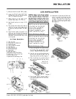
Diagram 4

Diagram 2

Diagram 1

Diagram 3

LOG INSTALLATION

unwrap them. The logs are fragile, handle 

with care - 

DO NOT FORCE

 into position.

2)

  Place the rear log, carefully sliding it down 

onto the pins, with the flat side of the log 

facing the back of the unit. See diagram 1.

3)

  Place the left front log, carefully sliding it 

down onto the left pins of the front burner. 

See diagram 2.

WARNING:  Dangerous operating conditions 

may occur if these logs are not positioned 

in their  approved  locations.   Read  the  in-

structions below carefully and refer to the 

diagrams. If logs are broken do not use the 

unit until they are replaced. Broken logs can 

interfere with the pilot and burner operation.


U28-2:

 The gas log kit contains the following:

 a)

  Front Right Log - Part # 902-020

 b)

  Front Left Log - Part # 902-021

 c)

  Rear log - Part # 902-022

 d)

  Embers  - Part # 902-151 (1 bag)


e)

  Lava - Part # 902-154 (1 bag)

 (Part #: 560-935 for set of three logs)


U43-3:

 The gas log kit contains the following:

 a)

  Front Right Log - Part # 902-245

 b)

  Front Left Log - Part # 902-244

 c)

  Rear log - Part # 902-246

 d)

  Embers - Part # 902-151 (2 bag)


e)

  Lava - Part # 902-154 (1 bag)

 (Part #: 653-930 for set of 3 logs)

1) 

Remove the logs from the box and carefully  

INSTALLATION

1)

  Make sure the valve is in the "OFF" position.

2)

  Loosen the "IN" (# 7) and/or "OUT" (# 6) 

pressure  tap(s),  turning  counterclockwise 

with a 1/8" wide flat screwdriver.

3)

  Attach  manometer  to  "IN"  and/or  "OUT" 

pressure tap(s) using a 5/16" ID hose.

4)

  Light the pilot and turn the valve to "ON" 

position.

5)

  The pressure check should be carried out 

with the unit burning and the setting should 

be within the limits specified on the safety 

label.

6)

  When  finished  reading  manometer,  turn 

off the gas valve, disconnect the hose and 

tighten the screw (clockwise) with a 1/8" flat 

screwdriver. 

Screw should be snug, but do 

not over tighten.

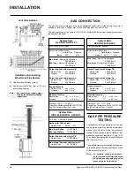
S.I.T. Valve Description

1)

  Gas cock knob

2)

  Manual high/low adjustment

3)

  Pilot Adjustment

4)

  Thermocouple Connection

5)

  Main Operator

6) 

Outlet Pressure Tap

7)

  Inlet Pressure Tap

8)

  Pilot Outlet

9)

  Main Gas Outlet

10)

 Flange Securing Screw Holes

11)

 Alternative TC Connection Point

12)

 Thermoelectric Unit

13)

 Additional Valve Mounting Hole

4)

  Place the right front log, carefully sliding  it 

down onto the right pins of the front burner. 

See diagram 3.

5)

  Distribute the embers along the front burner 

but do not cover the burner ports and around 

the logs. Place the embers on the floor of 

the firebox. Place the lava on the burner 

tray in front of the left and right front logs. 

See diagram 4.


Note:  Do not 

force logs down.

Summary of Contents for U28-LP2

Page 1: ... any appliance Do not touch any electrical switch do not use any phone in your build ing Immediately call your gas supplier from a neighbour s phone Follow the gas supplier s instructions If you cannot reach your gas sup plier call the fire department 908 728 FIREPLACE PRODUCTS INTERNATIONAL LTD 6988 Venture St Delta BC Canada V4G 1H4 MODELS U28 NG2 Natural Gas U28 LP2 Propane U43 NG3 Natural Gas ...

Page 2: ... all the warmth and charm of a woodstove at the flick of a switch The models U43 NG3 U43 LP3 U28 NG2 and U28 LP2 of this series has been approved by Warnock Hersey for both safety and efficiency As it also bears our own mark it promises to pro vide you with economy comfort and security for many trouble free years to follow Please take a moment now to acquaint yourself with these instructions and t...

Page 3: ... U28 24 Warranty Warranty 27 Safety Label Safety Label U43 NG3 4 Safety Label U43 LP3 5 Safety Label U28 NG LP2 6 Installation General Installation Information 7 Installation Checklist 8 Minimum Clearances to Combustibles 8 U28 Optional Long Side Doors 9 Optional Outside Air 9 Outside Air through Bottom of Pedestal 9 Outside Air through Rear of Pedestal 9 Draft Hood 9 High Elevation 9 Venting 9 Ve...

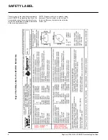
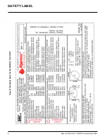
Page 4: ...ave printed a copy of the contents here for your review The safety label is located on the inside of the drop down pedestal door NOTE Regency units are constantly being improved Check the label on the unit and if there is a difference the label on the unit is the correct one SAFETY LABEL Copy of the Safety Label for the U43 NG3 Natural Gas ...

Page 5: ...Regency U28 2 U43 3 ULTIMATE Freestanding Gas Heater 5 SAFETY LABEL Copy of the Safety Label for the U43 LP3 Propane ...

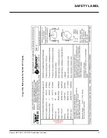
Page 6: ...6 Regency U28 2 U43 3 ULTIMATE Freestanding Gas Stove SAFETY LABEL Copy of the Safety Label for the U28 NG2 U28 LP2 ...

Page 7: ...doing required maintenance INSTALLATION AND REPAIR SHOULD BE DONE BY A QUAL IFIED SERVICE PERSON THE APPLIANCE SHOULD BE IN SPECTED BEFORE USE AND AT LEAST ANNUALLY BY A PRO FESSIONAL SERVICE PERSON MORE FREQUENT CLEANING MAY BE REQUIRED DUE TO EXCESSIVE LINT FROM CAR PETING BEDDING MATERIAL ETC IT IS IMPERATIVE THAT CONTROL COMPARTMENTS BURNERS AND CIRCULATING AIR PASSAGEWAYS OF THE APPLIANCE BE ...

Page 8: ...anceiscorrectifthetwo clearancesdonotcoincide Forexample if the appliance is set as indicated in one of the figures but the connector is too close move the stove until the correct clearance to the connector is obtained This unit can be installed on a solid com bustible surface like a wood floor This unit canalsobeinstalleddirectlyoncarpeting or vinyl when the bottom pedestal cover plate provided w...

Page 9: ...t follow current CAN CGA B149 1 In U S A for installations above 2000 ft refer to currentANSI Z223 1 Sc8 8 1 2a appendix F for resizing orifice U28 OPTIONAL LONG SIDE DOOR INSTALLATION INSTALLATION VENTING This heater is a vented appliance and must be connectedtoachimney flueinaccordancewith the installation codes Note The rear pedestal cover plate is only required when outside air is being used I...

Page 10: ...3 NG3 For 2 000 4 500 feet altitude Burner Inlet Orifice Sizes Natural Gas Burner 33 Max Input Rating 34 000 Btu h Min Input Rating 18 000 Btu h Output Capacity with blower Off Natural Gas 24 820 Btu h Max Output Capacity with blower On Natural Gas 26 180 Btu h System Data U43 NG3 U43 LP3 GAS CONNECTION The gas line can be rigid pipe or to make installation easier use a listed flexible connector i...

Page 11: ...f 3 logs 1 Remove the logs from the box and carefully INSTALLATION 1 Make sure the valve is in the OFF position 2 Loosen the IN 7 and or OUT 6 pressure tap s turning counterclockwise with a 1 8 wide flat screwdriver 3 Attach manometer to IN and or OUT pressure tap s using a 5 16 ID hose 4 Light the pilot and turn the valve to ON position 5 The pressure check should be carried out with the unit bur...

Page 12: ...u may want to angle the plate slightly so the door closes easier 4 The latches should already be at the proper setting If they are too hard or too easy to close you may want to adjust them by loosening the latch catch See diagram 3 Diagram 2 U43 Diagram 3 U43 Diagram 2 U28 Diagram 3 U28 INSTALLATION 5 Remove the blue plastic protective coating from the glass 6 Test the seal around the door by plac...

Page 13: ...Regency U28 2 U43 3 ULTIMATE Freestanding Gas Heater 13 WIRING DIAGRAM U43 3 WIRING DIAGRAM U28 2 INSTALLATION ...

Page 14: ...PTIONAL REMOTE CONTROL Use the Regency Remote Control Kit approved for this unit Use of other systems may void your warranty The remote control kit comes with a hand held transmitter areceiverandawallmountingplate 1 Choose a convenient location on the wall to install the receiver and the receptacle box protection from extreme heat is very important Run wires from the fireplace to that location use...

Page 15: ... and understand these Instructions before operating this appliance 2 Check to see that all wiring is correct and enclosed to prevent possible shock 3 Check to ensure there are no gas leaks 4 Make sure the three pieces of door glass are properly positioned Never operate the appliance with any of the glass removed or with the door open 5 Verify that all venting and the cap is unob structed 6 Verify ...

Page 16: ...16 Regency U28 2 U43 3 ULTIMATE Freestanding Gas Stove COPY OF THE LIGHTING PLATE INSTRUCTIONS OPERATING INSTRUCTIONS ...

Page 17: ...ulator or valve Unit Body Firebox Different types and thicknesses of steel will expand and contract at different rates resulting in some cracking and ticking sounds will be heard throughout the cycling process AERATION ADJUSTMENT The burner aeration is factory set but may need adjusting due to either the local gas supply or altitude U43 NG3 Natural Gas 3 16 open U43 LP3 Propane 1 2 open U28 NG2 Na...

Page 18: ...viceperson toensure that the flow of combustion and ventilation air is not obstructed During the annual service call the burners should be removed from the burner tray and cleaned Replace the embers do not block the pilot or burner ports 5 Keep the area near the appliance clear and free from combustible materials gasoline and other flammable vapours and liquids 6 Verify proper operation after serv...

Page 19: ...e door gasket 3 Removethenutsholdingtheglassretainers in place 4 Remove the glass retainers sides top and bottom and the door catch plate 5 Replace the glass The glass must have gasketing around it 6 Reverse the previous steps replace the retainers and fasten with the nuts but do not overtighten as this can break the glass Note the door catch plate fits on top of the left side retainer 7 Put gaske...

Page 20: ...ide Seediagram below REMOVING VALVE If your valve requires maintenance or replace ment follow these instructions NOTE Always shut off the gas supply before removing the valve 1 Openfrontpedestaldoorandunhookchain You may want to put a soft cloth on the base of the unit so that when the pedestal door is open it doesn t scratch the paint See diagram below 2 Undo the six screws holding the control pa...

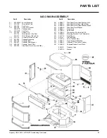
Page 21: ... Door 17 904 257 Pedestal Door Magnet 18 590 126 Pedestal Cover Plate 19 593 520 Side Panel Door Assy Left Side 20 650 527 Side Panel Door Hinge Bracket Left 21 593 522 Side Panel Door Assy Right Side 22 650 528 Side Panel Door Hinge Bracket Right 23 904 258 Side Panel Door Magnet 24 948 241 Door Latch 25 910 250 Spill Switch 27 910 233 Thermodisc Fan Auto On Off 28 650 086 Mounting Bracket Fan Th...

Page 22: ...Fan Speed Controller 120 V 593 524 P Valve Assembly Natural Gas 593 526 P Valve Assembly Propane 60 910 378 Valve S I T Natural Gas 910 380 Valve S I T Propane 904 688 32 Orifice N G 904 641 50 Orifice Propane 71 591 200 Log Stand Assy Rear 72 910 034 Pilot Assy SIT 3 flame N G 910 035 Pilot Assy SIT 3 flame Propane 653 930 Pkg Log Set 75 902 245 Front Log Right 76 902 244 Front Log Left 77 902 24...

Page 23: ...oor Complete 650 972 Gold Wrap Door Complete 650 970 Gold Panel Door Complete 101 650 920 Door Gasket Kit 105 936 264 Ceramic Paper 106 940 226 P Side Glass 107 936 243 Glass Gasket 108 940 227 P Mitred Centre Glass 111 936 262 Door Frame Fibre Paper 112 650 236 Door Glass Extrusion 208 940 235 P Wrap Glass 309 940 225 P Panel Centre Glass PARTS LIST ...

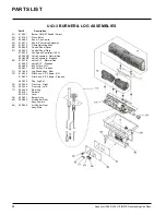
Page 24: ...8 728 Manual 948 116 Logo Plate 2 560 920 Top Bottom Gold Louvers set 560 922 Top Bottom Black Louvers set 5 910 199 Wire Holder Clip 6 910 179 Snap Bushing 9 560 055 Fan Access Door 10 560 030 Gasket for Fan Access Door 560 517 P Fan Assembly 11 910 331 P Fan Motor 120 Volt 12 910 794 Power Cord 120 Volt 13 910 178 Grommet for Power Cord 14 904 531 Split Plastic Bushing 15 560 525 Pedestal Assemb...

Page 25: ...ly Natural Gas 562 526 P Valve Assembly Propane 60 910 378 Valve S I T Natural Gas 910 380 Valve S I T Propane 904 593 40 Orifice N G 904 390 52 Orifice Propane 71 560 072 Log Stand Assembly Rear 72 910 034 Pilot Assy SIT 3 flame N G 910 035 Pilot Assy SIT 3 flame Propane 560 935 Log Set 75 902 020 Front Log Right 76 902 021 Front Log Left 77 902 022 Rear Log 902 151 Embers 902 154 Lava 78 651 580...

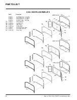
Page 26: ...0 926 Black Mitred Door Complete 560 932 Gold Wrap Door Complete 560 928 Gold Panel Door Complete 101 650 920 Door Gasket Kit 105 936 264 Ceramic Paper 106 940 236 P Side Glass 107 936 243 Glass Gasket 108 940 237 P Centre Glass 111 936 262 Door Frame Fibre Paper 112 560 032 Door Glass Extrusion 208 940 238 P Wrap Glass PARTS LIST ...

Page 27: ...ough an accredited distributor or agent provided that the defective part be returned to the distributor or agent Transportation Prepaid if requested Exclusions This limited Lifetime Warranty does not extend to or include paint door or glass gasketing or trim It does not cover installation and operational related problems such as over firing downdrafts or spillage caused by environmental conditions...

Page 28: ...____________________________________ Serial No ___________________________________________________________ ___________________________________________________________________ Printed in Canada Regency fireplace products are designed with reliability and simplicity in mind In addition our internal Quality Assur ance Team carefully inspects each unit thoroughly before it leaves our door Fireplace Pr...

Reviews: