


50
F O R M
DVR
®
2400 and DVR
®
2500 Digital Voltage Regulator
Installation, Operation and Maintenance Manual
SB0056E
Revised
November 2018
Regal Beloit America, Inc.
100 East Randolph Street
Wausau, WI 54402-8003
www.regalbeloit.com/Brands/
Marathon-Generators
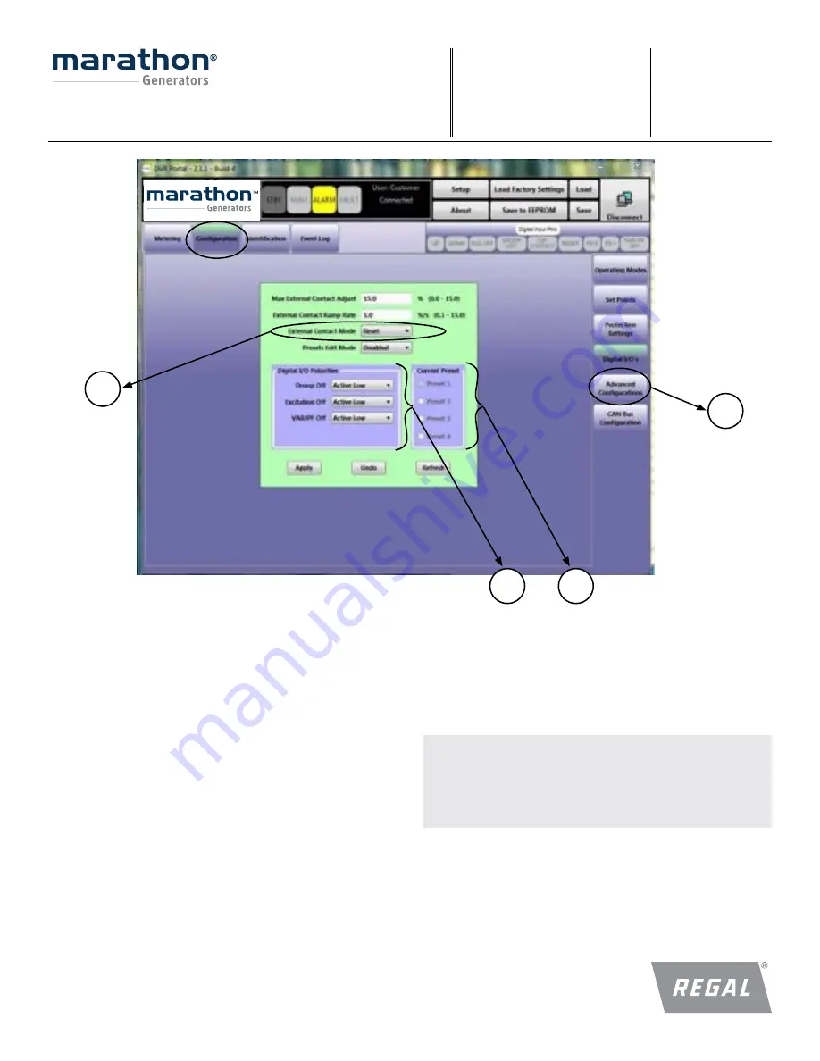
DIGITAL I/O (6)
This panel contains configurations related to the regulator digital inputs
and output.
External Contact Mode (6a)
This field provides users a way to configure UP/DOWN contact mode.
Setting this to RETAIN will save contact offset after a change is made to
the UP/DOWN contact. The DVR
®
regulator clears the offset after power
cycle if this is set to RESET.
Current Preset (6b)
These radio buttons show which preset is currently active in the 2500.
These provide users the ability to set the configurations for each of the
presets using these radio buttons. Here the steps that need to be followed
in order to edit the preset configurations.
a. Place the regulator is stand-by mode
b. Connect to regulator through the DVRPortal
™
software
c. Set “Preset Edit Mode” to “Enable”
d. Select the preset that you would like to edit (6b)
e. Navigate through various tabs and modify the configurations
f. Once the configurations are modified to this particular preset, hit
“Save to EEPROM”
g. Repeat steps “c - f” for other presets
Note:
Configurations will be lost if current preset is changed in the
DVRPortal software program
before saving to EEPROM.
Digital I/O Polarity (6c)
This panel provides users the ability to change polarity of the digital inputs
to either Active Low or Active High.
Example:
Default configuration of Excitation OFF contact is Active Low
(excitation turned OFF when contact between EXC and GND is closed).
If the user configures this to Active High, excitation will be disabled
when the contact is Active High (excitation turned OFF when contact Is
open between EXC and GND).
Notes:
1. Digital I/O polarity changes are allowed in Preset 1 only.
2. EXC_OFF polarity change won’t take effect until a power cycle
3. Presets 2 through 4 will have same settings as Preset One (1).
6
6b
6c
6a


