


Engines & Controls
3-9
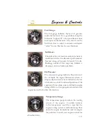
Fuel Gauge:
The fuel gauge indicates the level of gasoline
inside the fuel tank. It is a good idea to keep the
fuel tanks “topped off ” when possible to reduce
fuel vapors inside the tank. Also, do not run the
fuel level close to empty to ensure an adequate
“safety” factor. Practice the one third.rule.
Temperature Gauge
The temperature gauge monitors the cooling
system of the engine. A sudden increase
in the temperature could be a sign that the
engine cooling system is malfunctioning. Shut
down the engine immediately and investigate
the problem. Consult your engine manual for
allowable limits.
Oil Pressure:
The oil pressure gauge indicates the pressure of
the oil inside the engine lubrication system. A
drop in oil pressure may be an indication of a low
oil situation or a leak. Continued operation of the
engines with low oil pressure could lead to engine
damage. Refer to the appropriate manufacturer’s
engine manual for further information.
Volt Meter:
If installed, the volt meter monitors the battery
condition as well as the alternator performance.
Normal voltage is between 12.0 and 15.0 volts.
Readings outside of this range may indicate a
charging system or battery problem.
Summary of Contents for 3200 Bowrider
Page 1: ...INT 1 OWNER S MANUAL 3200...
Page 2: ...REGAL 321302 3200 Bowrider OWNER S MANUAL 10 2012...
Page 7: ...INT 7 Introduction THIS PAGE IS LEFT INTENTIONALLY BLANK...
Page 18: ...INT 18...
Page 38: ...1 16 CHAPTER 1 NAVIGATION LIGHT RULES...
Page 41: ...1 19 Safety On Board...
Page 109: ...Vessel Operation 5 9...
Page 150: ...CHAPTER 6 6 18 Canvas Typical PowerTower In Up Position w Sunshades...
Page 155: ...Equipment Operation 6 23 Canvas Typical Storage Mooring Cover...
Page 182: ...CHAPTER 6 6 50 Typical Hinged Power Tower Actuator Hydraulic Ram Typical Power Tower...
Page 191: ...Equipment Operation 6 59...
Page 192: ...CHAPTER 6 6 60...
Page 193: ...Equipment Operation 6 61...
Page 194: ...CHAPTER 6 6 62...
Page 195: ...Equipment Operation 6 63...
Page 196: ...CHAPTER 6 6 64...
Page 197: ...Equipment Operation 6 65...
Page 199: ...Equipment Operation 6 67...
Page 200: ...CHAPTER 6 6 68...
Page 278: ...CHAPTER 9 Notes...
Page 290: ...11 4 TYPICAL LABEL PLACARD LOCATION PowerTower...
Page 292: ...6 3200 BOW RIDER DECK HARDWARE 1 0F 2...
Page 297: ...11 3200 BOW RIDER TYPICAL EPA COMPLIANT FUEL TANK INSTALLATION...
Page 299: ...13 3200 BOW RIDER COLD WATER SYSTEM RUNS...
Page 300: ...14 3200 BOW RIDER ELECTRIC TOILET W OVERBOARD DISCHARGE...
Page 301: ...15 3200 BOW RIDER ELECTRIC TOILET W DECK PUMP OUT...
Page 306: ...3200 BOW RIDER DC HEAD PANEL 20...
Page 307: ...3200 BOW RIDER HELM SWITCH PANEL 21...
Page 308: ...3200 BOW RIDER HELM BREAKER PANEL 22...
Page 309: ...3200 BOW RIDER VOLVO IGN MERC ANALOG EVC 23...
Page 310: ...3200 BOW RIDER IPA VOLVO MERC ANALOG 24...
Page 311: ...3200 BOW RIDER IPA VOLVO MERC ANALOG W GARMIN 25...
Page 312: ...3200 BOW RIDER BATTERY MANAGEMENT PANEL 26...
Page 313: ...3200 BOW RIDER AFT SWITCH PANEL 27...
Page 314: ...3200 BOW RIDER WINDLASS PANEL 28...
Page 315: ...3200 BOW RIDER HEIGHT DIMENSIONS 30 1 1 2 54 1 4 101 3 4 8 5 3 4 3 1 4 45 3 4 58 3 15 12...
Page 316: ...3200 BOW RIDER STANDARD SEATING POSITIONS 31...


