


CHAPTER 6
6-32
Keel Offset.
By pressing the “ON/OFF MODE” keypad again displays
the “KL” keel offset setting. It can be set so the depth
fi
nder shows
the depth below the transducer or the depth under the keel. Press the
“UP” or “DOWN” arrow keypads to adjust the reading to the desired
depth no further than 19.9 feet.
An example would be if the keel bottom is 3 feet below the transducer
and you desire the depth sounder to read the depth below the keel, the
display should be adjusted to read 3.0 FT.
Note:
Once the keel offset is programmed, the shallow and deep alarms
will be energized by the depth under the keel.
Units.
Pressing the “ON/OFF MODE” keypad again displays “UN”
on the LCD indicating the units mode.
Press either the up or down arrow keypads to set the units desired to
(FT) feet, (M) meters, or (F) fathoms. Once these units are set, they will
remain the same for all modes. By pressing the “ON/OFF MODE”
keypad again returns the depth
fi
nder to normal operation.
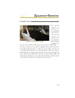
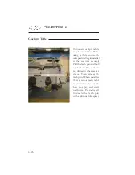
Note: Near the keel (center
of boat bottom)the depth
sounder transducer is lo-
cated. It bounces a constant
signal off the bottom and
sends it to the dash head
unit. Never use bottom
paint on the hull side of
the transducer since it will
effect the unit’s operation.
Typical
Transducer
Summary of Contents for 3200 Bowrider
Page 1: ...INT 1 OWNER S MANUAL 3200...
Page 2: ...REGAL 321302 3200 Bowrider OWNER S MANUAL 10 2012...
Page 7: ...INT 7 Introduction THIS PAGE IS LEFT INTENTIONALLY BLANK...
Page 18: ...INT 18...
Page 38: ...1 16 CHAPTER 1 NAVIGATION LIGHT RULES...
Page 41: ...1 19 Safety On Board...
Page 109: ...Vessel Operation 5 9...
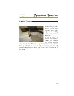
Page 150: ...CHAPTER 6 6 18 Canvas Typical PowerTower In Up Position w Sunshades...
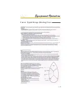
Page 155: ...Equipment Operation 6 23 Canvas Typical Storage Mooring Cover...
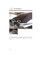
Page 182: ...CHAPTER 6 6 50 Typical Hinged Power Tower Actuator Hydraulic Ram Typical Power Tower...
Page 191: ...Equipment Operation 6 59...
Page 192: ...CHAPTER 6 6 60...
Page 193: ...Equipment Operation 6 61...
Page 194: ...CHAPTER 6 6 62...
Page 195: ...Equipment Operation 6 63...
Page 196: ...CHAPTER 6 6 64...
Page 197: ...Equipment Operation 6 65...
Page 199: ...Equipment Operation 6 67...
Page 200: ...CHAPTER 6 6 68...
Page 278: ...CHAPTER 9 Notes...
Page 290: ...11 4 TYPICAL LABEL PLACARD LOCATION PowerTower...
Page 292: ...6 3200 BOW RIDER DECK HARDWARE 1 0F 2...
Page 297: ...11 3200 BOW RIDER TYPICAL EPA COMPLIANT FUEL TANK INSTALLATION...
Page 299: ...13 3200 BOW RIDER COLD WATER SYSTEM RUNS...
Page 300: ...14 3200 BOW RIDER ELECTRIC TOILET W OVERBOARD DISCHARGE...
Page 301: ...15 3200 BOW RIDER ELECTRIC TOILET W DECK PUMP OUT...
Page 306: ...3200 BOW RIDER DC HEAD PANEL 20...
Page 307: ...3200 BOW RIDER HELM SWITCH PANEL 21...
Page 308: ...3200 BOW RIDER HELM BREAKER PANEL 22...
Page 309: ...3200 BOW RIDER VOLVO IGN MERC ANALOG EVC 23...
Page 310: ...3200 BOW RIDER IPA VOLVO MERC ANALOG 24...
Page 311: ...3200 BOW RIDER IPA VOLVO MERC ANALOG W GARMIN 25...
Page 312: ...3200 BOW RIDER BATTERY MANAGEMENT PANEL 26...
Page 313: ...3200 BOW RIDER AFT SWITCH PANEL 27...
Page 314: ...3200 BOW RIDER WINDLASS PANEL 28...
Page 315: ...3200 BOW RIDER HEIGHT DIMENSIONS 30 1 1 2 54 1 4 101 3 4 8 5 3 4 3 1 4 45 3 4 58 3 15 12...
Page 316: ...3200 BOW RIDER STANDARD SEATING POSITIONS 31...


