Description of the device
— 03.09.2020 - Rev. A
English — 5
4.3.2
Type code
No.
Reflexomat RS type key
1
Control unit
designation
2
Number of
compressors
Reflexomat RS 90 / 1, RG 1000 l, RF 1000 l
3
"RG" primary vessel
1 2 3 4 5
6
4
Nominal volume
5
"RF" secondary
vessel
6
Nominal volume
4.4
Function
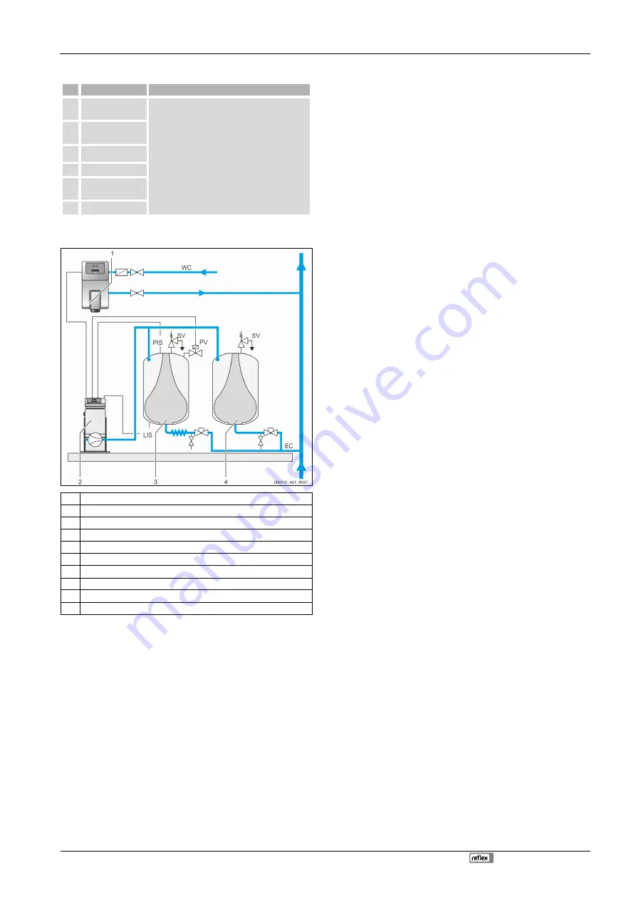
1
Make-up with water using "Fillcontroll Auto"
2
Control unit
3
Primary vessel as expansion vessel
4
Secondary vessel as additional expansion vessel
WC Make-up pipe
PIS Pressure sensor
SV
Safety valve
PV Solenoid valve
LIS Pressure load cell
EC
Expansion pipe
Expansion vessels
One primary vessel and multiple optional secondary vessels may be connected. A
membrane separates the vessels into an air and a water space, preventing the
penetration of atmospheric oxygen into the expansion water. The primary vessel
is connected to the control unit downstream and connected hydraulically to the
plant system. The pressure is protected at the air side by the "SV" safety valves of
the vessels.
Control unit
The control unit contains one or optionally two compressors "CO" and the "Reflex
Control Touch" controller. Via the primary vessel, the pressure is measured with
the "PIS" pressure sensor and the water level with the "LIS" pressure load cell
and the values then displayed in the controller display.
Pressurisation
•
If the water is heated, it expands and the pressure increases in the plant
system. If the pressure set at the controller is exceeded, the "PV" solenoid
valve opens and discharges air from the primary vessel. Water flows from
the system into the primary vessel and the pressure drops in the plant
system until the pressure in the plant system and the primary vessel is
equalised.
•
The pressure in the plant system drops when the water cools. When the
pressure drops below the set value, the "CO" compressor cuts in and
delivers compressed air into the primary vessel. This displaces water out of
the primary vessel into the plant system. The pressure in the facility system
rises.
Make-up
The addition of more water is controlled within the controller. The "LIS" pressure
load cell determines the water level and sends this value to the controller of the
pressure maintaining station. This controls an external make-up. Water is directly
added into the system in a controlled manner by monitoring the make-up time
and the make-up cycles.
If the water level in the primary vessel falls below minimum, a fault message is
output from the controller and shown in the display.
Note!
Additional equipment for topping up water, see chapter 4.6 "Optional
equipment and accessories" on page 5 .
4.5
Scope of delivery
The scope of delivery is described in the shipping document and the content is
shown on the packaging.
Immediately after receipt of the goods, please check the shipment for
completeness and damage. Please notify us immediately of any transport
damage.
Basic pressure-maintaining equipment:
•
Control unit with one or two compressor(s) including compressed air
line(s).
•
Primary tank with flexible water connection.
•
"LIS" pressure load cell for level sensing.
4.6
Optional equipment and accessories
•
Secondary vessels with connection sets for the primary vessel.
•
For make-up with water
–
Make-up without pump:
•
Solenoid "Fillvalve" with ball valve and Reflex Fillset for make-
up with drinking water.
–
Make-up with pump:
•
Reflex Fillcontrol Auto, with integrated pump and a system
separation vessel or Auto Compact
•
For make-up and degassing with water:
–
Reflex Servitec S
–
Reflex Servitec 35- 95
•
Fillset for make-up with drinking water.
–
With integrated system separator, water meter, dirt trap and locking
mechanisms for the "WC" make-up line.
•
Fillset Impulse with FQIRA+ contact water meter for make-up with
drinking water.
•
Fillsoft for softening or desalination of the make-up water from the
drinking water network.
–
Fillsoft is installed between Fillset and the device. The device
controller evaluates the make-up quantities and signals the required
replacement of the softening cartridges.
•
Optional expansions for Reflex controllers:
–
I/O module for standard communication, see chapter 5 "I/O module
(optional expansion module)" on page 6 .
–
Master-Slave-Connect for master controllers for maximum 10
devices.
–
Bus modules:
•
Profibus DP
•
Ethernet
•
Diaphragm rupture monitor
Note!
Separate operating instructions are supplied with accessories.
Cooke Industries - Phone: +64 9 579 2185 Email: [email protected] Web: www.cookeindustries.co.nz


