6
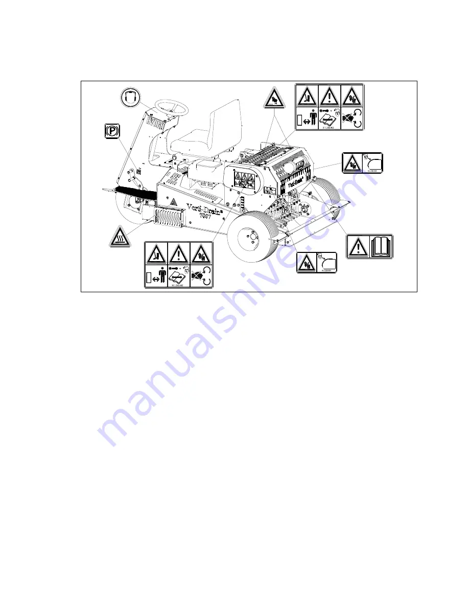
(7) Location of safety stickers.
(Fig. 8)
Fig. 8
Used oil/grease is harmful to the environment; dispose of it according to locally
applicable regulations.
Page 1: ...AND TO ACHIEVE THE BEST RESULTS IT IS OF THE UTMOST IMPORTANCE TO READ THIS USER MANUAL CAREFULLY BEFORE USING THE VERTI DRAIN 0718 English Manual code 911 120 402 User manual and parts handbook Verti...
Page 2: ...d This card should be returned for handling any future claims This user manual offers many instructions numbered in sequence This sequence should be observed An asterisk indicates a safety instruction...
Page 3: ...ded 3 All persons whom the owner assigns to operate maintain or repair the Verti Drain must read and have completely understood the operating manual and in particular the section Safety Instructions T...
Page 4: ...fore carrying out maintenance adjustments and repairs always first switch off the engine and remove the key from the ignition Fig 2 Fig 2 When carrying out any maintenance or repairs ensure you use or...
Page 5: ...ed During operation ensure there are NO persons in the danger area except the driver of the Verti Drain because they may be injured by moving parts Fig 3 fig 3 fig 4 Remain at least 4 metres away Fig...
Page 6: ...6 7 Location of safety stickers Fig 8 Fig 8 Used oil grease is harmful to the environment dispose of it according to locally applicable regulations...
Page 7: ...erti Drain unit troubleshooting 23 14 0 Maintenance 24 15 0 EU certificate 24 16 0 Technical information 25 16 1 The crankshaft 25 16 1 1 Replacement of a crank crank crank bearing 25 16 1 2 Releasing...
Page 8: ...mm x 1 250 mm 81 2 x 44 x 50 Maximum tine size Solid 12 x 150 mm 1 2 x 6 Hollow 19 x 150 mm 3 4 x 6 Engine 18 HP electric starter max 3000 rpm Engine oil SAE 30 Hydraulic oil Shell Naturelle Fluid HF...
Page 9: ...23 13 12 11 10 9 8 7 6 5 4 3 15 16 17 18 19 14 22 21 20 25 26 27 28 29 24 Fig 10 The machine can be prepared as follows 1 Remove all separate parts from the machine 2 Mount the two back wheels the two...
Page 10: ...ide The end of shaft 13 must be the same as the end of conical bush 23 Check the working of the brake by manually energising handle 19 The handle should move smoothly If the brake works correctly atta...
Page 11: ...Check if the speed pedal will have free play if so adjust item nr 2 so that you do not have any free play left in the pedal Move the pedal a few times forward and backward and check if it still comes...
Page 12: ...ast 4 metres from the machine Stop the engine before carrying out repairs or adjustments 3 Safety sticker 911 280 404 the back cover must always be closed and undamaged during operation of the machine...
Page 13: ...dance indicators 20 Adjustable scrapers 21 Starter cord 22 Choke 23 Blocking mechanism for folding the seat 24 Hour revolution counter 25 Blocking strip for the Verti Drain unit A number of important...
Page 14: ...oller by turning clock or counter clockwise the spindles 3 Each rotation is 4 mm 0 16 The sticker 4 on the side of the machine gives the depth setting 6 When the required height has been reached re ti...
Page 15: ...uired tine angle 6 Re tighten the nuts 1 once the correct angle has been achieved An angle of 90 degrees means almost no tine movement This is required for hollow tines and is advised for the 8 mm 5 1...
Page 16: ...the case consult section 12 0 Troubleshooting 4 Next drive forwards to aerate the surface 5 The speed can now be increased to the maximum Do not drive in reverse with the Verti Drain in the lowest pos...
Page 17: ...until the conditions are more favourable 8 When the soil is very compact use shorter tines or adjust the operating depth 8 0 Transportation of the Verti Drain The Verti Drain may not be driven over t...
Page 18: ...ieved To adjust this pedal you must first unscrew the knob 3 and next the pedal must be turned to the required position using the adjustment handle 4 Next the knob 3 must be re tightened Table 1 speci...
Page 19: ...tes in such a way that when the brake pedal 1 has been pressed the parking brake 2 will also have been pressed To ensure that the Verti Drain is on the parking brake 2 it must be completely pressed Th...
Page 20: ...is a blocking mechanism on the machine to avoid this situation When the Verti Drain is no longer operational the blocking strip 1 can be turned towards the Verti Drain with the Verti Drain in the top...
Page 21: ...Drain is removed from the ground is to disconnect the V belt restart the machine and next to lift the Verti Drain from the ground Switch the machine off to again tension the V belt The machine can now...
Page 22: ...ed Forward movement Accelerator is not working at its best Check whether the threaded rods have been adjusted correctly See Section 15 7 Check the spring If necessary replace it The parking brake is n...
Page 23: ...ing depth Heavy conditions Adjust the operating depth Water the soil Damage to the drawbars Bend break Machine not at 90 degrees Central bar bent Bearing tubes worn Tines touch the ground when driving...
Page 24: ...the loose bolts nuts with the correct torque Check the hydraulic oil level Fill the battery and charge it 4 hours at 3 amps Check the V belt tension on Verti Drain unit Inspect the machine carefully...
Page 25: ...ome loose from the big end That is if the crank bearings the crank bearing fittings or the big end pin holes in the crank are damaged Replace the crank the bearing as soon as possible to prevent addit...
Page 26: ...must be checked regularly for looseness Do not mount the cranks on the wrong side of the machine See the parts page for the correct part numbers 800 Nm 590 lbf ft Lock washer 100 Nm 73 8 lbf ft A 100...
Page 27: ...is replaced so no extra tension is created in the total element assembly Every pre tension in the element assembly will reduce the life of the bearing and can also damage other parts 16 4 TIMING OF TH...
Page 28: ...the idler 3 can be moved down 6 Remove all bushes and bolts around the pulleys including on the Verti Drain side that lock the V belt 6 7 Loosen the chain coupling between engine and pump 8 Remove the...
Page 29: ...ct tension Follow the following steps to achieve this See fig 24 1 Remove the nuts 2 and the safety cap 1 2 Loosen the nut on the tensioning pulley 3 and move the pulley down until the correct pre ten...
Page 30: ...is correct Should this not be the case this can be adjusted by sliding the adjustment plate 2 The threaded rod 3 must be turned for as long as necessary so that the bridging arm 6 of the pump is put i...
Page 31: ...ensure that leaks and therefore any tracks in the field are avoided 16 9 Adjusting the pressure of the hydraulic system The pressure of the hydraulic system is controlled through a pressure relieve v...
Page 32: ...number of bolts and nuts INSTALLATION OF THE TURF HOLD DOWN KIT see fig 28 The ordered set comes with plates 2 Fasten the plates to the main beam with bolt 3 and nut 1 Align the plates with the tines...
Page 33: ...to adjust the operation depth such that the penetration depth is slightly deeper than the length of the roots This gives the roots a chance to grow deeper Aerate deeper the next time By using this met...
Page 34: ...st be used first to break the ground open Wetting the soil or adjusting the operating depth can also help solve this problem 17 1 3 MULTI TINE KIT You can aerate with smaller tines than 12 mm with a m...
Page 35: ...lso be driven and the machine will therefore have more grip and a more effective transmission in the field The kit consists of a hydraulic motor a three way valve for switching from two wheel to three...