background image

Redexim


10

6.  ATTACHING AND DETACHING THE MACHINE 

Attaching and detaching the machine has to be done carefully. Follow the instructions below:  


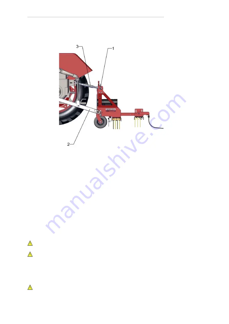
Figure 2 


6.1. Attaching the machine 

Prior to attaching the machine, check the following the points: 
 

-

  Check whether the machine is undamaged and whether it is safe to attach and use 

the machine. 

-

  Check whether the bolts and nuts are tightened with the correct torque. 

-

  Check whether all safety stickers are on the machine and whether these are 

undamaged and easily readable. Never


use the machine if it has damaged or 

unreadable stickers. 

 
The machine should be attached to the tractor in the following manner: 
 

1.  Remove the


3-point pins 

(1)

 from the machine 

(see Figure 2)

2.  Carefully drive the tractor backwards until the lifting arms 

(2) 

can be attached to the 

machine. 


!! 

Make sure that the tractor and the machine cannot move while you are attaching  

them !! 


!! 

Switch off the tractor engine before attaching the machine !! 


3.  Attach the lifting arms 

(2)

 to the machine using the 3-point pins. Lock the pins using 

the r-clips. 

4.  Set the stabilizer to a sideways stroke of 100 mm. 
5.  Mount the top rod 

(3)

 onto the tractor and attach it to the machine. 

6.  Adjust the top rod in such a manner that the machine is horizontal. 


!! 

Make sure that the 3-point pins are locked using the r-clips !! 


7.  Start the tractor and lift the machine off the ground. 

Summary of Contents for Combi-Groom

Page 1: ...User Manual and Parts Book Combi Groom REDEXIM Kwekerijweg 8 3709JA Zeist The Netherlands Tel 31 0 306 933 227 E mail redexim redexim com Internet www redexim com 1808 English 962 120 000...

Page 2: ...roduct COMBI GROOM WITH A MACHINE NUMBER AS INDICATED ON THE MACHINE AND INDICATED IN THIS MANUAL to which this declaration refers complies with the stipulation of the 2006 42 EC machine directive and...

Page 3: ...ts that are used All information and technical specifications provided at the moment that this document is published are the most recent ones Design specifications may be changed without prior notice...

Page 4: ...RS 8 5 FIRST INSTALLATION 9 6 ATTACHING AND DETACHING THE MACHINE 10 6 1 Attaching the machine 10 6 2 Detaching the machine 11 7 ADJUSTING THE WORKING DEPTH 11 8 TRANSPORT 12 9 PUTTING THE MACHINE INT...

Page 5: ...the safety must be rectified immediately The user is obliged to check the machine for visible damage and defects before using the machine For safety reasons it is not permitted to make changes or adju...

Page 6: ...Used oil grease is harmful to the environment Dispose of these substances according to the regulations that apply in your location 1 3 Using the machine Attach the machine to the towing vehicle accor...

Page 7: ...ed 610 mm behind the lifting eyes Working width 2 038 m 80 Working depth 0 35 mm 0 1 38 Speed Maximum 12 km h 7 5 mph Weight 195 kg 430 lbs Dimensions L x W x H 2 01 x 1 3 x 0 9 m 80 x51 x35 Three poi...

Page 8: ...e and must be replaced if they have become damaged 933 280 402 In case of maintenance adjustments and repair always switch OFF the engine of the towing vehicle Keep a distance of minimum 4 metres if t...

Page 9: ...m 300 kg 662 lbs 1 Attach a cable to the lifting eye 1 2 Lift the machine including the pallet approx 50 mm 2 off the ground 3 Loosen the pallet by removing the 3 point pins 2 4 Pull the pallet from u...

Page 10: ...he machine should be attached to the tractor in the following manner 1 Remove the 3 point pins 1 from the machine see Figure 2 2 Carefully drive the tractor backwards until the lifting arms 2 can be a...

Page 11: ...4 Loosen the lowest arms 2 5 Start the tractor and drive off 7 ADJUSTING THE WORKING DEPTH The working depth can be adjusted by setting the running wheels The front side of the machine will become hig...

Page 12: ...20 degrees for this machine Always go from top to bottom 2 Are there hard objects in the ground If so use the machine at adjusted speed 3 Is there danger of flying objects e g golf balls that distract...

Page 13: ...book for mounting this option onto the Combi Groom Figure 4 10 2 Magnetic beam A magnetic beam is available in order to remove steel particles such as nails screws and shoe studs from the ground This...

Page 14: ...0 3 Towing hook If the towing vehicle is not fitted with a three point system to lift the Combi Groom the Combi Groom can be equipped with a towing hook You can order this option under number 262 120...

Page 15: ...ly over its entire length and whether these are still present After every use Cleaning Clean the machine using water If you clean with high pressure you should avoid the lubricated components 12 TROUB...

Reviews: