background image

www.redbackaudio.com.au

Redback® Proudly Made In Australia

10

Redback® A 4505C

 Lockdown Timer with Network Access

Select the CLOCK ADJUST sub menu by presing the “Enter” button.
After selecting this option, the screen as shown in Fig 2.3c should appear. 


Fig 2.3c

The cursor will be positioned over the hour section of the time. Use the up and down buttons to change the hour and then 
press the “Enter Button” to confirm the hour. The cursor will move to the minutes section of the time. Use the up and down 
buttons to change the minutes and then repeat the process again for the seconds. Once the seconds have been updated 
the cursor will move to the day of the week. Use the up and down buttons again to change the day and then press enter 
to confirm. The time is now set.

2.4 PROGRAMMING THE TIMING EVENTS USING THE SUPPLIED PC SOFTWARE

Refer to the Redback Timer Programming Guide.

2.5 PROGRAMMING THE TIMING EVENTS USING THE FRONT BUTTONS

In order to set up the timing events, the station (or event) times will need to be programmed. This can be achevied by using 
the buttons on the front of the unit.

Select the “TIMES ADJUST” option from the menu (refer to figure 2.3b).


This option allows the user to enter the Station 

(Event) information which includes the event “Turn on time”, “Period” and “Output”.
After selecting this option, the screen as shown in Fig 2.5a should appear. 

Fig 2.5a

The top left text is the time event number. Up to 50 events can be programmed into the A 4500C. Pressing the “up” and 
“down” buttons at this stage will move up and down through the events 1- 50. The top right text indicates that TIME1 
(Event1) is currently disabled. The bottom left text refers to the time this event will happen (i.e. the “Start” Time).
Press the “Enter” button to edit this event, or press the “Menu” button to exit.
Pressing the Enter button will take you to the “Editing Time” screen (Refer to fig 2.5b). This is where the event “Start” time 
is entered. 

Fig 2.5b

The cursor will be positioned over the hour section of the time. Use the up and down buttons to change the hour and then 
press the “Enter Button” to confirm the hour. The cursor will move to the minutes section of the time. Use the up and down 
buttons to change the minutes and then repeat the process again for the seconds. Once the seconds have been updated 
the screen will change to the “Period” set screen (Refer to fig 2.5c) . This is where the duration of the event is recorded.

Fig 2.5c

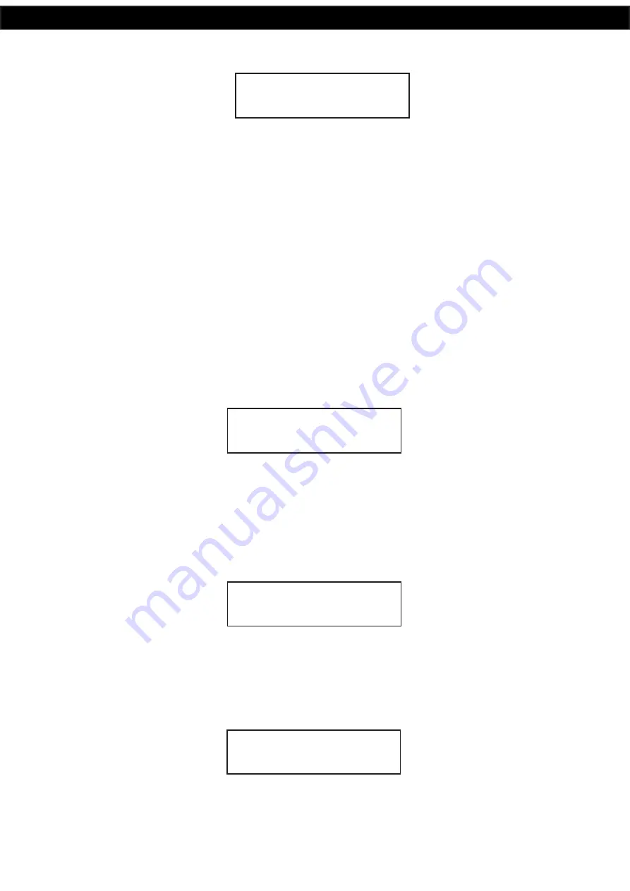
EDITING CLOCK    

00:00:00   Mon

TIME1    DISABLED 

00:00:00    EDIT?  

EDITING     TIME1 

START 00:00:00

EDITING     TIME1 

PERIOD   00:00:00

Summary of Contents for A 4505C

Page 1: ...E Please read these instructions carefully from front to back prior to installation They include important setup instructions Failure to follow these instructions may prevent the unit from working as...

Page 2: ...d users reliable products of high build quality with local product support We believe there is significant added value for customers when purchasing an Australian made Redback amplifier or PA product...

Page 3: ...vents Using The Supplied PC Software 10 2 5 Programming The Timing Events Using The Front Button 10 2 6 Deleting A Programmed Time 11 2 7 Reset All Programmed Times 11 2 8 EV Chanegover 12 2 9 Play Pr...

Page 4: ...ockdown Fire and Bell tones and the cancel function are triggered by the front switches or by the rear terminal con tacts for remote activation Switched 24V DC Out connections are provided for Bell Lo...

Page 5: ...of the Music Folders 5 99 is active 6 Menu and Navigation Switches These switches are used to navigate the menu functions of the unit 7 Isolate Switch This switch is used to isolate the timing functi...

Page 6: ...3 0 for details 6 Backup Battery Switch Use this switch to activate the backup battery Note The backup battery only backs up the current time 7 Backup Battery Replace this battery with a 3V CR2032 onl...

Page 7: ...be triggered by a remote switch or other closing contact 17 Cancel Contact These contacts are for remote triggering of the cancel function These could be triggered by a remote switch or other closing...

Page 8: ...icated by the illumination of the relevant front panel indicator Note 2 To cancel a tone either use the remote cancel contacts or the front cancel button Note the cancel button will need to be depress...

Page 9: ...5 EV CHANGEOVER 00 00 00 Mon NO TIME__00 00 00 Menu Main Screen Press the UP and DOWN buttons to scroll up and down Enter Press the ENTER button to make your selection Menu Press the MENU button to ex...

Page 10: ...is option allows the user to enter the Station Event information which includes the event Turn on time Period and Output After selecting this option the screen as shown in Fig 2 5a should appear Fig 2...

Page 11: ...sets each day ON or OFF Use the up and down buttons to set the day to Y for ON and N for OFF Once the days of the week are set press the enter button to confirm and be returned to the main menu Repea...

Page 12: ...als up to 600 seconds NOTE If the changeover time is set to 0 the changeover will be de activated and therefore the unit will not switch over from the Alert cycle to the Evac cycle automatically 2 9 P...

Page 13: ...olume setting on the individual volume control attenuator Lockdown Fire 24V Out These contacts are for switched 24V outputs whenever the Lockdown or Fire tones are activated These may be used to run e...

Page 14: ...To Ethernet Converter setup is complete and all required connections made the unit should now be acces sible via the PC software Refer to the supplied Software Programming Guide for more information N...

Page 15: ...Lockdown Fire Bell and cancel functions of the Redback A 4505C Connection is made from the A 2069 to the A 4505C via a minimum of 8 wires as shown in Fig 4 2 If standard Cat5 6 cable is used for the w...

Page 16: ...wall plate are connected to the Lockdown Fire and Bell 24V outputs of the Redback A 4505C The cancel LED is not connected A mimimum of eight wires can be used if the ground connections of the Lockdown...

Page 17: ...te Wall Plate Evac Alert Chime Cancel Mic Volume To Paging Console To Wall Plate Adapter CR2032 Backup Battery Holder Use 3V CR2032 Battery Only N C N O L R Audio Out Prebell Level V Over Level DIP Sw...

Page 18: ...e for download on the microsoft website CHECK SD CARD HAS BEEN INSERTED CORRECTLY CHECK SD FORMATTED CORRECTLY CHECK MP3 FILES INSTALLED CHECK FORMAT OF MP3 It cannot be WAV or AAC MP3 files cannot be...

Page 19: ...verified before switching any system component on Failure to follow the correct wiring configuration may result in damage to system components 6 0 FIRMWARE UPDATE It is possible to update the firmware...

Page 20: ...act CONTROLS Lockdown Fire Rear Volume Voice over Rear Volume Bell Rear Volume Prebell Rear Volume Music Rear Volume Power On Off Switch Lockdown Switch Illuminated Push Switch Fire Switch Illuminated...

Reviews: