


For Sales and Support, Contact Walker EMD • Toll-free: (800) 876-4444 • Tel: (203) 426-7700 • Fax: (203) 426-7800 • www.walkeremd.com
4
EMC INSTALLATION GUIDELINES
Although this unit is designed with a high degree of immunity to
ElectroMagnetic Interference (EMI), proper installation and wiring methods
must be followed to ensure compatibility in each application. The type of the
electrical noise, source or coupling method into the unit may be different for
various installations. In extremely high EMI environments, additional measures
may be needed. Cable length, routing and shield termination are very important
and can mean the difference between a successful installation or a troublesome
installation. Listed below are some EMC guidelines for successful installation
in an industrial environment.
1. The unit should be mounted in a metal enclosure, that is properly connected
to protective earth.
a. If the bezel is exposed to high Electro-Static Discharge (ESD) levels, above
4 Kv, it should be connected to protective earth. This can be done by making
sure the metal bezel makes proper contact to the panel cut-out or connecting
the bezel screw with a spade terminal and wire to protective earth.
2. Use shielded
(screened)
cables for all Signal and Control inputs. The shield
(screen)
pigtail connection should be made as short as possible. The
connection point for the shield depends somewhat upon the application.
Listed below are the recommended methods of connecting the shield, in order
of their effectiveness.
a. Connect the shield only at the panel where the unit is mounted to earth
ground
(protective earth)
.
b. Connect the shield to earth ground at both ends of the cable, usually when
the noise source frequency is above 1 MHz.
c. Connect the shield to common of the unit and leave the other end of the
shield unconnected and insulated from earth ground.
3. Never run Signal or Control cables in the same conduit or raceway with AC
power lines, conductors feeding motors, solenoids, SCR controls, and
heaters, etc. The cables should be run in metal conduit that is properly
grounded. This is especially useful in applications where cable runs are long
and portable two-way radios are used in close proximity or if the installation
is near a commercial radio transmitter.
4. Signal or Control cables within an enclosure should be routed as far away as
possible from contactors, control relays, transformers, and other noisy
components.
5. In extremely high EMI environments, the use of external EMI suppression
devices, such as ferrite suppression cores, is effective. Install them on Signal
and Control cables as close to the unit as possible. Loop the cable through the
core several times or use multiple cores on each cable for additional protection.
Install line filters on the power input cable to the unit to suppress power line
interference. Install them near the power entry point of the enclosure. The
following EMI suppression devices
(or equivalent)
are recommended:
Ferrite Suppression Cores for signal and control cables:
Fair-Rite # 0443167251 (RLC #FCOR0000)
TDK # ZCAT3035-1330A
Steward #28B2029-0A0
Line Filters for input power cables:
Schaffner # FN610-1/07 (RLC #LFIL0000)
Schaffner # FN670-1.8/07
Corcom #1VB3
Corcom #1VR3
Note:
Reference manufacturer’s instructions when installing a line filter.
6. Long cable runs are more susceptible to EMI pickup than short cable runs.
Therefore, keep cable runs as short as possible.
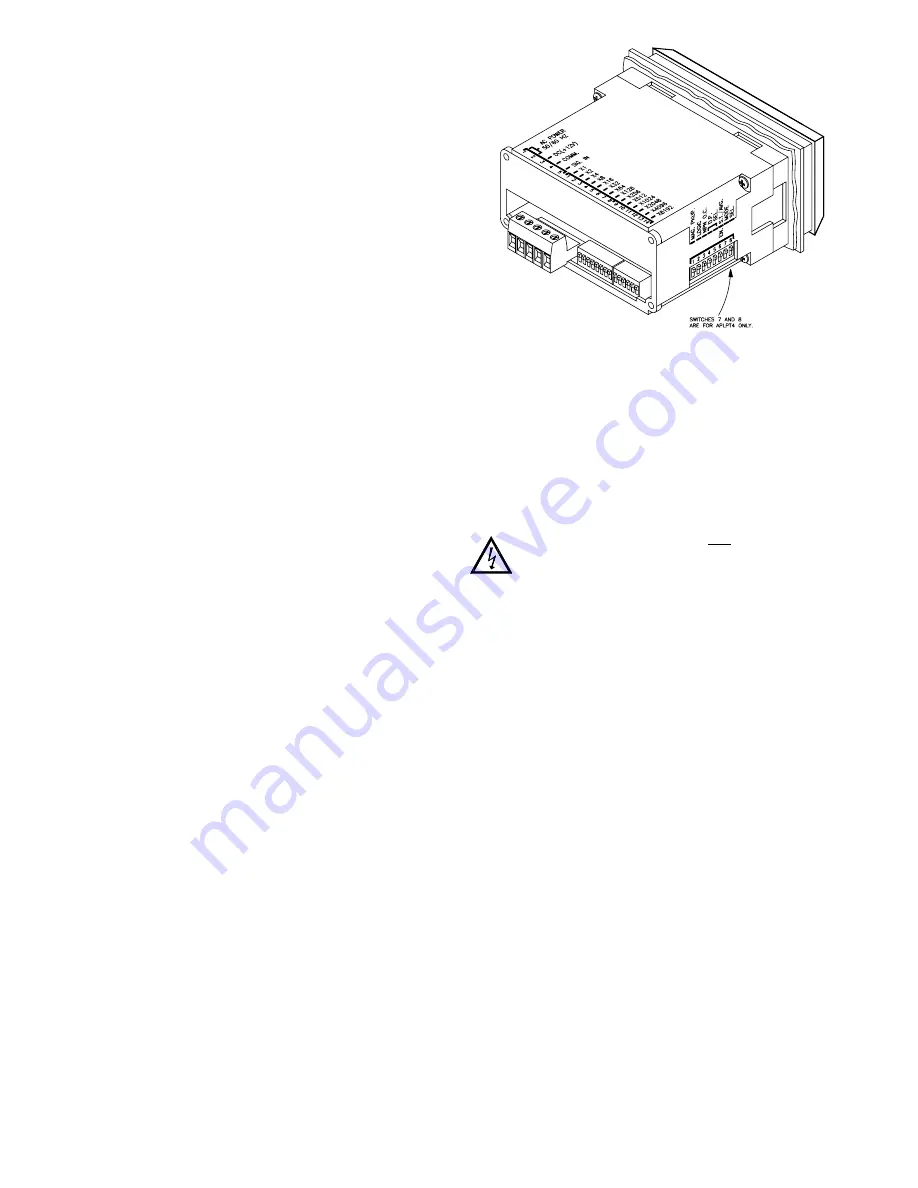
WIRING CONNECTIONS
As depicted in the drawing showing the rear view of the Apollo Process Time
Indicator, there is a terminal block where all wiring connections are made. All
conductors should meet voltage and current ratings for each terminal. Also
cabling should conform to appropriate standards of good installation, local
codes and regulations. It is recommended that power supplied to the unit (AC
or DC) be protected by a fuse or circuit breaker. Remove the block for easy
access to the terminal screws. To remove the block, pull from the back of the
block until it slides clear of the terminal block shroud.
Enclosed with the PBLPT module is an adhesive backed label(s) showing the
terminal block pin-out. This label is for wiring reference only, do not use for
specifications. This label should be applied to the appropriate location by the user.
CAUTION: The terminal block should NOT be removed with power
applied to the unit. The module should not be removed from the
LDD with power applied to the LDD or the module.
INPUT & POWER CONNECTIONS
Primary AC power is connected to Terminals 1 and 2
(marked A.C. Power,
located on the left-hand side of the block)
. For best results, the AC power should
be relatively “clean” and within the specified ±10% variation limit. Drawing
power from heavily loaded circuits or from circuits that also power loads that
cycle on and off should be avoided.
Terminal 3 is the
“DC” (+12 V)
terminal. This terminal is for sensor supply
and can provide up to 100 mA of current. An ex11 V to +14 VDC can
also be applied to this terminal to power the unit in the absence of A.C. power.
Terminal 4 is the
“COMM.” (common)
terminal, which is the common line to
which the sensor and other input commons are connected. Terminal 5 is the
“SIG. IN” (signal in)
terminal. When the signal at this terminal goes low, a
count will be registered in the unit.
(See “Input Ratings” under
“Specifications” section.)
REAR PANEL DIP SWITCHES
As can be seen from the rear of the unit, there is a row of 14 DIP switches
located beside the input and power terminal block. All of these DIP switches are
Display Multiplier Increment Total
(DMIT)
switches. When the switch is
“ON”
,
it will multiply the measured time between input pulses by the display multiplier
it represents.