Chapter 1. Red Hat Cluster Suite Overview
7
•
Configured with CMAN/DLM —
fenced
, the fence daemon, performs fencing.
•
Configured with GULM servers — GULM performs fencing.
When the cluster manager determines that a node has failed, it communicates to other
cluster-infrastructure components that the node has failed. The fencing program (either
fenced
or GULM), when notified of the failure, fences the failed node. Other cluster-
infrastructure components determine what actions to take — that is, they perform any
recovery that needs to done. For example, DLM and GFS (in a cluster configured with
CMAN/DLM), when notified of a node failure, suspend activity until they detect that the
fencing program has completed fencing the failed node. Upon confirmation that the failed
node is fenced, DLM and GFS perform recovery. DLM releases locks of the failed node;
GFS recovers the journal of the failed node.
The fencing program determines from the cluster configuration file which fencing method
to use. Two key elements in the cluster configuration file define a fencing method: fencing
agent and fencing device. The fencing program makes a call to a fencing agent specified
in the cluster configuration file. The fencing agent, in turn, fences the node via a fencing
device. When fencing is complete, the fencing program notifies the cluster manager.
Red Hat Cluster Suite provides a variety of fencing methods:
•
Power fencing — A fencing method that uses a power controller to power off an inop-
erable node
•
Fibre Channel switch fencing — A fencing method that disables the Fibre Channel port
that connects storage to an inoperable node
•
GNBD fencing — A fencing method that disables an inoperable node’s access to a
GNBD server
•
Other fencing — Several other fencing methods that disable I/O or power of an inoper-
able node, including IBM Bladecenters, PAP, DRAC/MC, HP ILO, IPMI, IBM RSA II,
and others
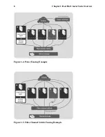
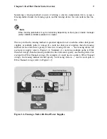
Figure 1-4 shows an example of power fencing. In the example, the fencing program in
node A causes the power controller to power off node D. Figure 1-5 shows an example of
Fibre Channel switch fencing. In the example, the fencing program in node A causes the
Fibre Channel switch to disable the port for node D, disconnecting node D from storage.
Summary of Contents for CLUSTER SUITE - FOR RHEL 4
Page 1: ...Red Hat Cluster Suite for RHEL 4 Overview ...
Page 4: ......
Page 10: ...vi About This Document ...
Page 47: ...Chapter 1 Red Hat Cluster Suite Overview 37 Figure 1 25 Cluster Configuration Structure ...
Page 62: ...52 Chapter 1 Red Hat Cluster Suite Overview ...
Page 72: ...62 Chapter 2 Red Hat Cluster Suite Component Summary ...


