


TM-4412 Page 9
D502K 5+4
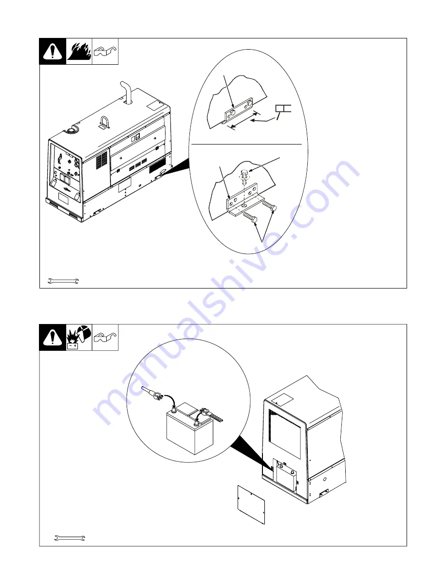
4-3.
Mounting Welding Generator
803 122 / Ref. 802 169-B
Y
Do not weld on base. Weld-
ing on base can cause fuel
tank fire or explosion. Weld
only on the four mounting
brackets or bolt unit down.
1
Mounting Bracket
2
1/2 in Bolt And Washer
(Minimum – Not Supplied)
3
3/8-16 x 1 in Screws
(Supplied)
To Weld Unit In Place:
Weld unit to truck or trailer only at
the four mounting brackets.
To Bolt Unit In Place:
Remove hardware securing the
four mounting brackets to the base.
Reverse brackets and reattach to
base with original hardware.
Mount unit to truck or trailer with 1/2
in (12 mm) or larger hardware (not
supplied).
Tools Needed:
9/16 in
1
1
2
3
Welding Unit In Place
Bolting Unit In Place
4-4.
Connecting The Battery
1/2 in
–
+
Y
Connect Negative (–) Cable Last.
Tools Needed:
802 168-E / Ref. 202 705 / 802 313 / S-0756-C
.
Reinstall cover after connecting battery.
Summary of Contents for D502K 5+4
Page 4: ......
Page 19: ...TM 4412 Page 15 D502K 5 4 Notes...
Page 25: ...TM 4412 Page 21 D502K 5 4 SECTION 7 MAINTENANCE 7 1 Maintenance Label...
Page 58: ...TM 4412 Page 54 D502K 5 4 Notes...
Page 61: ...TM 4412 Page 57 D502K 5 4 206 628 A...
Page 81: ......


