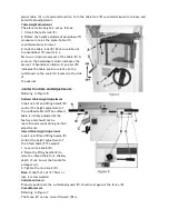


2. Remove two button head socket screws (C)
and upper back panel (D).
3. Remove four button head socket screws (O)
and lower back panel (P).
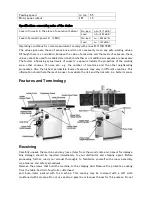
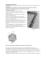
Cutterhead Drive Belt Replacement
4. Loosen four motor mount screws (L). Lift the
motor and rest it in the horizontal slot side of
the motor mount opening. This will create a
slack in the cutterhead drive belt (F).
5. Remove the cutterhead drive belt (F) from
around the cutterhead pulley (E) and motor
pulley (M).
6. If the feed-roller belt (K) is to be replaced,
continue. Otherwise proceed to step 10.
Feed-roller Belt Replacement
Note:
If the feed-roller belt is to be replaced, steps
1
–
5 must be performed to remove the cutterhead
drive belt before the feed-roller belt can be
replaced.
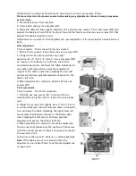
7.
Place the power feed handle (J) in the down
(off/disengaged) position, which provides belt
slack for the next step.
8. Remove the feed-roller belt (G) from around
the feed-roller pulley (K) and motor pulley (M).
9. Loop the new belt around the smaller (inner)
motor pulley (M) and feed-roller pulley (K).
Note:
The lower stretch of the feed-roller
pulley must be positioned between the beltbrake
plates (N).
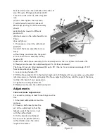
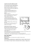
Concluding Steps
10. Replace the cutterhead drive belt (F) by looping it around the cutterhead pulley (E), then the
larger (outside) motor pulley (M).
11. Slide the motor so the mounting screws (L) rest back in the vertical slot openings, then tighten
the mounting screws.
12. Replace the lower back panel (P) and secure with four button head socket screws (O).
13. Replace the upper back panel (D) and secure with two
button head socket screws (C).
14. Replace the jointer fence assembly (A) and secure with
two lock handle assemblies (B).
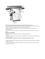
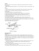
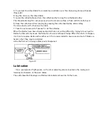
Planer Table Adjustment
Disconnect machine from power source before making any
adjustments.
Failure to comply may cause serious injury.
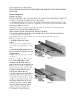
Checking Planer Table Parallel to Cutterhead
The planer table is set parallel to the cutterhead at
Summary of Contents for PT260
Page 25: ...Troubleshooting Performance Troubleshooting Jointer ...
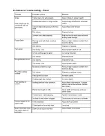
Page 26: ...Performance Troubleshooting Planer ...
Page 27: ...Mechanical Troubleshooting Planer Jointer ...
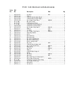
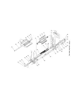
Page 28: ...PT 260 Cutter Block Guard and Outfeed Assembly ...
Page 30: ...PT 260 Cutter Block assembly ...
Page 32: ...PT 260 Base Assembly ...
Page 34: ...PT 260 Infeed Table Assembly ...
Page 36: ...PT 260 Drive and Motor Assembly ...
Page 38: ...PT 260 Thickness Table Assembly ...
Page 40: ...PT 260 Working Fence Assembly ...