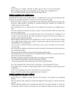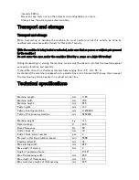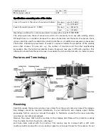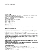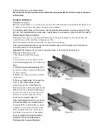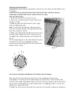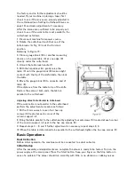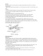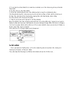
If alignment is required as determined in the previous section, proceed as follows:
Disconnect machine from power source before making any adjustments. Failure to comply may cause
serious injury.
1. Disconnect power from machine.
2. Unlock both cabinet lock handles (A2).
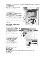
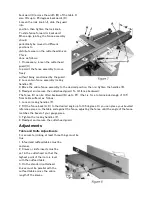
3. Raise the table (D) fully upright. Adjustment is performed by means of four setscrews (B2) that
adjusts the table pitch and tilt at the back (towards the fence) and two hex cap screws (A1) that
adjusts the table toward the front.
Adjustment can consist of a front adjustment, rear adjustment or (more probable) a combination of
both.
Rear adjustment
Tools required
–
13mm wrench, 4mm hex wrench
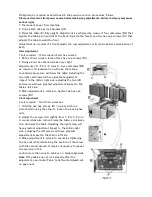
1. With a 13mm wrench, loosen three hex cap screws (B1).
2. Using a 4mm hex wrench, make very slight
adjustments of 1/8 to 1/4 turns to four setscrews (B2)
as required. A clockwise turn will raise the table; a
counterclockwise turn will lower the table. Adjusting the
two right setscrews will have greatest adjustment
impact to the table's right side; adjusting the two left
setscrews will have greatest adjustment impact to the
table's left side.
3. When adjustment is complete, tighten the hex cap
screws (B1)
Front adjustment
Tools required
–
two 13mm wrenches
1. Hold the hex cap screws (A1) in place with one
wrench while using the other to loosen the locking hex
nuts.
2. Adjust the screws (A1) slightly from 1/8 to 1/4 turn.
A counterclockwise turn will raise the table; a clockwise
turn will lower the table. Adjusting the right screw will
have greatest adjustment impact to the table's right
side; adjusting the left screws will have greatest
adjustment impact to the table's left side.
3. When adjustment is complete, secure by tightening
the hex nut while maintaining the position of the screw
with the second wrench. It may be necessary to repeat
the exercise in this
section more than once to achieve co-planar alignment.
Note:
If the tables do not lock properly after the
adjustment, see Jointer Table Lock Handle Adjustment
on page next.
Summary of Contents for PT260
Page 25: ...Troubleshooting Performance Troubleshooting Jointer ...
Page 26: ...Performance Troubleshooting Planer ...
Page 27: ...Mechanical Troubleshooting Planer Jointer ...
Page 28: ...PT 260 Cutter Block Guard and Outfeed Assembly ...
Page 30: ...PT 260 Cutter Block assembly ...
Page 32: ...PT 260 Base Assembly ...
Page 34: ...PT 260 Infeed Table Assembly ...
Page 36: ...PT 260 Drive and Motor Assembly ...
Page 38: ...PT 260 Thickness Table Assembly ...
Page 40: ...PT 260 Working Fence Assembly ...

