16
Fitting the Revolving Centre to the Tailstock
When turning between centres, the revolving centre should be used in
conjunction with the 4 prong drive centre. For details on turning between
centres, please refer to the
Intended use of the Lathe and Basic
Woodturning Instructions
chapter of the manual.
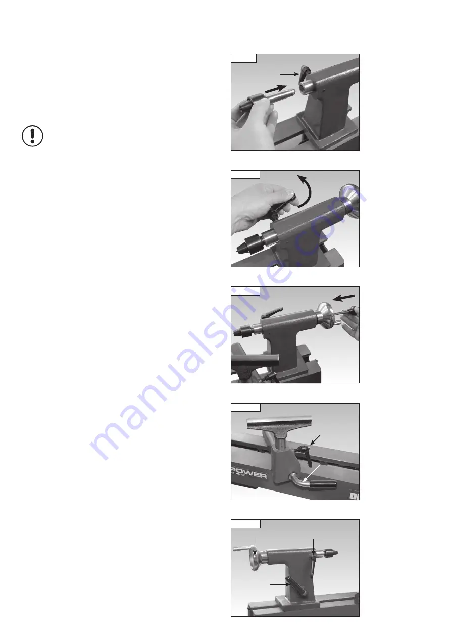
First ensure the tailstock spindle locking lever is loosened then insert the
revolving centre into the tailstock spindle,
Fig 10.9
, and tighten the locking
lever,
Fig 10.10
.
Please note: Before inserting tapered attachments into the
headstock or tailstock spindle, always ensure that the taper
is clean and free of any waste material that may cause
misalignment or vibration. Always fully seat the taper by
tapping it into place with a wooden mallet.
To remove the revolving centre from the tailstock spindle, loosen the
tailstock spindle locking lever, insert the knockout bar into the hole in the
centre of the tailstock hand wheel and give the revolving centre a sharp
knock to dislodge it from the tailstock, see
Fig 10.11
.
Adjusting the Tool Rest
To move the tool rest across the lathe bed, loosen the tool rest holder locking
lever by turning in an anti-clockwise direction, slide the tool rest holder to
the desired position and tighten the locking lever in a clockwise direction.
To adjust the height of the tool rest loosen the tool rest locking lever,
position as required and re-tighten,
Fig 10.12
.
Adjusting the Tailstock
Loosen the tailstock locking lever to move the tailstock along the lathe bed
to the desired position and tighten the lever,
Fig 10.13
.
To adjust the tailstock spindle position, loosen the tailstock spindle locking
lever and turn the hand wheel. When the tailstock spindle is in the desired
position, re-tighten the locking lever,
Fig 10.13
.
Adjustment of the Clamping Action of the Tool Rest Holder
and Tailstock
If the movement of the tool rest holder or tailstock is unsatisfactory, either
due to being too stiff and difficult to move or too easy to move and giving
inadequate locking, the clamping action can be adjusted. Please see the
maintenance section of the manual for full details.
10. Operation
i
Kg
Fig 10.11
Fig 10.10
Fig 10.12
Tool rest
locking
lever
Tool rest
holder
locking
lever
Fig 10.13
Tailstock spindle
locking lever
Tailstock
locking
lever
Hand wheel
Fig 10.9
Tailstock spindle
locking lever


