10
8. Assembly
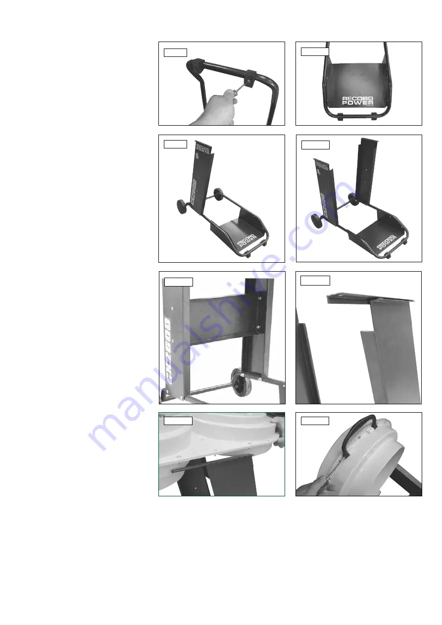
1. Attach the rubber feet to the wheel base using
the two M6 x 16mm screws provided as shown
in
Fig 8.1
. The two screw holes are located on
the underside of the wheelbase.
2. Attach the tray to the wheel base using the six
M5 x 16mm screws as shown in
Fig 8.2
, with
the Record Power logo facing the front of the
wheelbase, nearest to the rubber feet.
3. Using two of the M8 x 40mm screws, attach
the left hand panel to the left hand side of the
wheelbase as shown in
Fig 8.3
, ensuring the
panel is placed on top of the tubular frame of
the wheelbase. The top edge of the panel must
be closer to the front of the machine than the
bottom edge.
4. Using two more M8 x 40mm screws, attach
the right hand panel to the opposite side of
the frame as shown in
Fig 8.4
, again ensuring
the top of the panel is closer to the front of the
machine than the bottom.
5. Using the four M8 x 10mm screws attach
the cross brace panel to the left and right hand
panels with the open side of the panel facing the
front of the machine as in
Fig 8.5
.
6. Place the right angled bracket on top of the
right hand panel as shown in
Fig 8.6
, with
the short side facing the inside of the machine.
Ensure the bracket overhangs the front of the
panel as shown.
7. Carefully place the motor housing unit (with
the motor at the rear of the machine) onto the
bracket as shown in
Fig 8.7
and secure with
three of the M5 x 20mm screws.
8. Place the flat bracket on top of the left hand
panel and attach the motor housing unit using
the remaining M5 x 20mm screws.
9. Using the two 30mm screws, attach the
handle to the underside of the front of the motor
housing unit as shown in
Fig 8.8
.
Fig. 8.1
Fig. 8.3
Fig. 8.7
Fig. 8.4
Fig. 8.6
Fig. 8.5
Fig. 8.8
Fig. 8.2
Back
Front


