background image

12

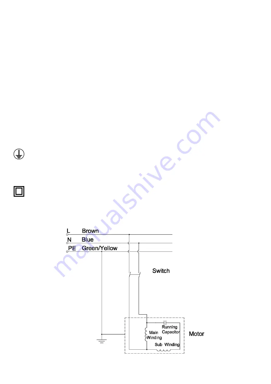
9. Electrical Connection & Wiring Diagram

Machines supplied for use in the UK are fitted with a 3 pin plug conforming 
to BS1363, fitted with a fuse conforming to BS1362 and appropriate to the 
current rating of the machine. 
Machines supplied for use in other countries within the European Union are 
fitted with a 2 pin Schuko plug conforming to CEE 7/7.
Machines supplied for use in Australia & New Zealand are fitted with a 3 pin 
plug conforming to AS/NZS3112.
In all cases, if the original plug or connector has to be replaced for any 
reason, the wires within the mains power cable are colour coded as follows:

230 V (Single Phase)
Brown: 

Live (L)

Blue:  

Neutral (N)

Green and Yellow:   Earth (E)

The wire coloured brown must always be connected to the terminal marked 
‘L’ or coloured red.
The wire coloured blue must always be connected to the terminal marked ‘N’ 
or coloured black.
The wire coloured green and yellow must always be connected to the 
terminal marked ‘E’ or with the earth symbol:

or coloured green / green and yellow.  
It is important that the machine is effectively earthed. Some machines will be 
clearly marked with the double insulated logo:

In this case there will not be an earth wire within the circuit.
In the case of the BS1363 plug for use in the UK, always ensure that it is 

fitted with a fuse conforming to BS1362 appropriate to the rating of the 
machine. If replacing the original fuse, always fit a fuse of equivalent rating 
to the original. Never fit a fuse of a higher rating than the original. Never 
modify the fuse or fuse holder to accept fuses of a different type or size.
Where the current rating of the machine exceeds 13 A at 230 V, or if the 
machine is designated for use on a 400 V 3 phase supply a connector 
conforming to BS4343 (CEE17 / IEC60309) will be used.
230 V machines will be fitted with a blue 3 pin connector. The wiring for this 
type of this connector will be the same as shown above. 
400 V, 3 phase machines will be fitted with a red 4 or 5 pin connector. The 
wiring for this type of connector is as shown below:

400 V (3 phase)
Brown:  

Live (L1)

Black: 

Live (L2)

Grey: 

Live (L 3)

Blue: 

Neutral (N)

Green and Yellow:  Earth (E)

The wire coloured brown must always be connected to the terminal  
marked ‘L1’.
The wire coloured black must always be fitted to the terminal  
marked ‘L2’.
The wire coloured grey must always be connected to the terminal  
marked ‘L3’.
The wire coloured blue must always be connected to the terminal  
marked ‘N’ or coloured black.
The wire coloured green and yellow must always be connected to the 
terminal marked ‘E’ or with the earth symbol  
If in doubt about the connection of the electrical supply, always consult a 
qualified electrician.

Summary of Contents for CX2600

Page 1: ...egister this product please visit www recordpower info It is important to register your product as soon as possible in order to receive efficient after sales support and be entitled to the full 5 year guarantee Your statutory rights are not affected Please see back cover for contact details Important For your safety read instructions carefully before assembling or using this product Save this manu...

Page 2: ...ION WHEREVER THE WARNINGS ARE USED 1 Explanation of Symbols Mandatory Instructions i i i i i i i Read and fully understand the instruction manual before attempting to use the machine Indicates an instruction that requires particular attention Wear protective eyewear Use respiratory protective equipment Use suitable protective footwear Use hearing protection Use protective work gloves Warning i Kg ...

Page 3: ...ling of the machine apply In addition ensure that any vehicles or manual handling equipment used for transportation are of adequate specification 6 The machine should be level and stable at all times When using a leg stand or cabinet base that is designed to be fitted to the machine always ensure that it is securely fastened to the machine using the fixings provided If the machine is suitable to b...

Page 4: ... not held down to the table top Do not use another person as a substitute for a table extension or as additional support for a work piece that is longer or wider than the basic table or to help feed support or pull the work piece Do not attempt to machine more than one work piece at a time When feeding the work piece towards the blade or cutting tool never position your hands in direct line of the...

Page 5: ...commended by our Company may present a risk of personal injury or damage to the machine and invalidation of the warranty 32 Have your machine repaired by a qualified person This machine complies with the relevant safety rules and standards appropriate to its type when used in accordance with these instructions and with all of the standard safety guards and equipment in place Only qualified persons...

Page 6: ...t as there is a risk of combustion Doing so will invalidate the warranty and may result in damage to the machine or serious injury to the user Do not use the machine to pick up hazardous dust Do not pick up liquids and scrap metal such as nails and filings or any combustible substance If the hose becomes blocked switch the machine OFF immediately to prevent any damage to the machine and disconnect...

Page 7: ... been purchased from a retailer the 5 year guarantee is transferable and begins on the date of the first purchase of the Product and in the event of a claim under this guarantee proof of the original purchase date will be required to validate the warranty period 2 Claims Procedure 2 1 In the first instance please contact the Authorised Dealer who supplied the Product to you In our experience many ...

Page 8: ...or 0 4 kW Weight 25 kg Capacity 80 litres Bag diameter 330 mm Size H1850 x W440 x L830 mm Sound power level 140 dB Sound pressure level 90 dB A Motor Rating Plate B Filter Bag C Motor D On Off Switch E Collection Bag F Hose G Optional Cartridge Filter H Adaptor A C D E F H G B ...

Page 9: ... 20mm Coach Screws x6 7 M5 Nuts x6 8 30mm Screws x2 9 Cross Head Screws x6 10 Rubber Feet x2 11 M6 x 16mm Roundhead Screws x2 12 Filter Bag Support 13 Adjustable Hose Clip x2 14 Handle 15 Wheel base 16 Tray 17 Right Hand Side Panel 18 Left Hand Side Panel 19 Right Angled Bracket 20 Flat Bracket 21 Filter Bag 22 Plastic Collection Bag 23 Extraction Hose 24 Motor Housing Unit 25 Cross Brace Panel 26...

Page 10: ... 8 4 again ensuring the top of the panel is closer to the front of the machine than the bottom 5 Using the four M8 x 10mm screws attach the cross brace panel to the left and right hand panels with the open side of the panel facing the front of the machine as in Fig 8 5 6 Place the right angled bracket on top of the right hand panel as shown in Fig 8 6 with the short side facing the inside of the m...

Page 11: ...per opening of the motor housing unit and tighten the band as shown in Fig 8 11 13 Attach the plastic collection bag to the opening on the underside of the motor housing unit using the remaining tightening band as shown in Fig 8 12 14 Place the adjustable hose clip onto the end of the extraction hose as shown in Fig 8 13 Place the end of the hose onto the smaller opening on the underside of the mo...

Page 12: ...3 plug for use in the UK always ensure that it is fitted with a fuse conforming to BS1362 appropriate to the rating of the machine If replacing the original fuse always fit a fuse of equivalent rating to the original Never fit a fuse of a higher rating than the original Never modify the fuse or fuse holder to accept fuses of a different type or size Where the current rating of the machine exceeds ...

Page 13: ...e the blockage from the collection hose To re start the machine press the green button marked I on the switch In the Event of a Power Failure The machine is fitted with a no volt release NVR switch to protect the user against automatic starting of the machine when power is restored after a power failure In the event of a power failure first locate and rectify the source of the failure If the fault...

Page 14: ...14 12 Parts List Diagram ...

Page 15: ...ut M8 8 019 RDC100 17 Hose 1 020 RDC100 09 Clamping Band 2 021 RDC100T 04 Horizontal Plate 1 022 RDC100T 01 05 rubber foot 2 023 _6 washer 024 M6_16 screw 025 RDC100E 03 Right Side Panel 1 026 RDC100T 08 Turbo Fan 1 027 GB T5781 Hexagon Bolt M8_12 4 028 GB T826 1 Washer_8 4 029 GB T97 1 Washer_6 1 030 GB T14 Dome Head Squared Bolt_12 14 031 GB T845 Pan Head Tapping Screw St4 8_15 6 032 KJD12 Magne...

Page 16: ...tives MACHINERY DIRECTIVE 2006 42 EC LOW VOLTAGE DIRECTIVE 2006 95 EC ELECTROMAGNETIC COMPATIBILITY DIRECTIVE 2004 108 EC and conforms to the machinery example for which the EC Type Examination Certificate No AM501964980001 has been issued by TUV RHEINLAND Product Service GmbH at Tillystrasse 2 90431 Nürnberg Germany and complies with the relevant essential health and safety requirements Signed Da...

Page 17: ...17 ...

Page 18: ...18 ...

Page 19: ...19 ...

Page 20: ...k Eire Record Power Ltd Centenary House 11 Midland Way Barlborough Links Chesterfield Derbyshire S43 4XA Telephone 01246 571 020 www recordpower co uk Australia Tools 4 Industry Po Box 3844 Parramatta 2124 Tel 1300 124 422 Fax 1800 262 725 www recordpower com au New Zealand Tools 4 Industry Po Box 276079 Manukau City 2241 Tel 0800 142 326 Fax 09 2717 237 www recordpower co nz Made in China ...

Reviews: