
MAINTENANCE & SERVICE
Air Handling Unit
Temovex Blue 4
REC Indovent AB, Box 37, SE-431 21 Mölndal, Sweden
|
+46-31-675500
|
www.rec-indovent.se
17
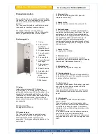
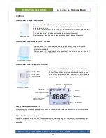
Cleaning
For best possible performance and a long life, the
AHU should be kept clean. Please see instructions
below on how to clean fans and heat exchanger.
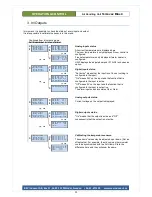
Changing filters
There are two filters in this AHU: exhaust air filter
and supply air filter (fresh air).
Both filters should be changed at least once a year,
and more often if need be. Do not wash the filters,
but exchange them for new ones.
To buy new filters, please contact the local dealer in
your country
or order from
www.rec-indovent.se
NOTE! The Temovex AHU must be fitted
with the Temovex filters listed on page 1 of this
manual. If the unit operates without filters, the
performance will be affected adversely and fans and
heat exchanger may be seriously damaged.
·
Cut off the power.
·
Open the unit door.
·
Remove Cover plate.
·
Remove EPP spacer by
pulling straight out.
·
Remove the old outdoor air
filter.
·
Release the inner cover by
turn the two hooks. Remove
the cover. (Behind the cover
is the exhaust air filter).
·
Remove the old exhaust air
filter.
·
Clean accessible surfaces if necessary.
·
Fit the new filters and cover in reverse order.
(The shortest filter first).
·
Close the unit door.
·
Turn on the power.
The unit operates even if the filters are dirty, but the
performance would be less good; energy
consumption increases and heat recovery
decreases.
To turn off/aknowledge filter alarm, see Ch 5.
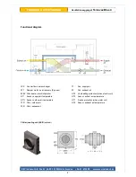
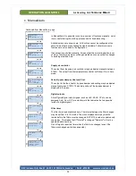
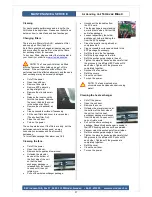
Cleaning the fans
.
·
Cut off the power.
·
Open the unit door.
·
Remove both upper and lower cover.
·
Unfasten the elevator
device at the bottom of
the front side of the unit,
so that the heat
exchanger package is
released from the topunit.
Loosen until it can not
rotate more.
·
Pull out the whole exchanger package.
·
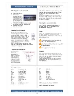
Unconnect the fan cables from
the PC board.
·
The fan package is now standing
on rails at both sides. Pull out the
entire fan package.
·
Loosen respectively fan holder
and take out holder inkluding fan
from the EPP package.
·
Clean the impeller using a brush or
compressed air.
·
Clean accessible surfaces and ducts in the
EPP package if necessary.
·
Refit the fans in the fan package.
·
Refit the fan package on the rails.
·
Refit the exchanger package in the unit.
·
Tighten the elevator device and be careful that
the grooves in the different EPP units will fit
each other. Tighten until the grooves are
completely together.
·
Reconect the fan cables.
·
Refit the covers.
·
Close the unit door.
·
Turn on the power.
NOTE! The fans must under no
circumstances be cleaned under running
water!.
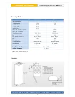
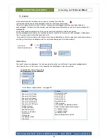
Cleaning the heat exchanger
·
Cut off the power.
·
Open the unit door.
·
Remove the cover.
·
Unfasten the elevator device at
the bottom of the front side of
the unit, so that the heat
exchanger package is released
from the topunit. Loosen until it
can not rotate more.
·
Pull out the whole exchanger
package. Respectively exchanger is sealed in
their EPP housing and can not be separated.
·
Vacuum clean the exchangers from all sides.
·
Refit the exchanger package in the unit.
·
Tighten the elevator device and be careful that
the grooves in the different EPP units will fit
each other. Tighten until the grooves are
completely together.
·
Refit the cover.
·
Close the unit door.
·
Turn on the power.
!
!
Summary of Contents for G10125
Page 19: ...19 Notes...


