background image

9

Installation Guide 


Locate the reverse taillights wiring behind your reverse light. 
You may need to remove the interior panel in order to locate. 
You only need to attach the signal booster power wire to ONE 
of the reverse lights, not both. If you cannot manually locate 
the tail light cables, please contact the vehicle manufacturer or 
reference a wiring diagram for your vehicle

Determine the reverse light power wires for your car, designating 
the positive and negative wires. 

Connecting the Power Cables:
Red wire to reverse light’s Positive wire. Connect the camera’s 
Black Wire to reverse light’s Negative wire. (see Diagram C)

 Place the 

fi

 xed adapter from the Wireless Digital 

Transmitter Power Cable into the Wireless Digital Transmitter.

■ 

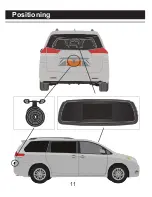
Determine the best place to mount the Transmitter. The 

Transmitter is not waterproof and needs to be protected.

At your taillight, remove the light bulb socket from the reverse 
light housing.

1

.

4.

2

.

3.

Determine the best route for the Camera Cable from the top of 
your license plate to the Transmitter. You may need to drill a 
small hole in the panel behind where the license plate is situated.

5.

Summary of Contents for RVS-091407

Page 1: ...Product Manual Installation Instructions Rear View Camera Systems Model RVS 091407 2009 2013 Rear View Safety Inc ...

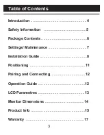
Page 2: ...y Information 5 Package Contents 6 Settings Maintenance 7 Installation Guide 8 Positioning 11 Pairing and Connecting 12 Operation Guide 12 LCD Parametres 13 Monitor Dimensions 14 Product Info 15 Warranty 17 Table of Contents ...

Page 3: ... is intended to be installed as a supplement aid to your standard rear view mirror that already exists in your vehicle The Backup Camera System should not be used as a substitute for the standard rear view mirror or for any other mirror that exists in your vehicle In some jurisdictions it is unlawful for a person to drive a motor vehicle equipped with a TV viewer or screen located forward of the b...

Page 4: ...itor while driving It may cause an accident Do not install the monitor where it may obstruct drivers view or obstruct an air bag device IN NO EVENT SHALL SELLER OR MANUFACTURER BE LIABLE FOR ANY DIRECT OR CONSEQUENTIAL DAMAGES OF ANY NATURE OR LOSSES OR EXPENSES RESULTING FROM ANY DEFECTIVE PRODUCT OR THE USE OF ANY PRODUCT Dropping the unit may cause possible mechanical failure Customer Service R...

Page 5: ...6 Package Contents ...

Page 6: ...ill enable for 30 seconds 2 System setting A Power saving push menu to change the selection and hold the Menu for long to exit B Brightness you can adjust the brightness of screen C Distance Grid select grid line on off D Default setting Cleaning If dirt rain or snow attaches to the camera the monitor may not clearly display objects Do not use alcohol benzene or thinner to clean the camera This wi...

Page 7: ...es a special pressurized mechanism see diagram A which clips onto the existing rear view mirror To hard wire the monitor see Diagram B locate a 12V in your fuse box and make sure the selected fuse is a ignition power source DC12V Red GND Black DC12V Red GND Black BMW male BMW female Dc female Dc male Diagram A Diagram B Diagram C ...

Page 8: ...gative wires Connecting the Power Cables Red wire to reverse light s Positive wire Connect the camera s Black Wire to reverse light s Negative wire see Diagram C Place the fixed adapter from the Wireless Digital Transmitter Power Cable into the Wireless Digital Transmitter Determine the best place to mount the Transmitter The Transmitter is not waterproof and needs to be protected At your tailligh...

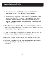
Page 9: ...icle in reverse If you have a clear picture put the vehicle back in park and turn the key to the off position You are now ready for final stepshousing 10 8 11 9 6 Plug the attached wire from the Camera into the Wireless Transmitter Ensure that the wires are not tangled While sitting in the driver s seat of the car with the key in the ignition position The monitor will automatically start when vehi...

Page 10: ...11 Positioning ...

Page 11: ...onitor and do the following step a Press Menu b Go to Pair Camera d The unit is now in pair mode if the unit was able to search and connect with the camera the display will show Pair OK If no camera is found then the display will show Timed Out 1 Power ON OFF The Dash or Mirror Monitor will automatically turn ON when it is connected to a power source and the camera is recieving power 2 Connection ...

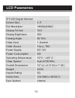
Page 12: ... Display Brightness 350 Viewing Angle 90 Min Video Input 1 channel Video Source 1Vp p 75Ω Power Supply DC 12V Power Consumption 5W Operating Temperature 10 C 65 C Video System Auto NTSC PAL Overall Dimensions 10 L x 3 5 H x 1 D Weight 400G Impact Rating 5G Active Area 154 08 H x 86 58 V Sync System Internal ...

Page 13: ...14 Monitor Dimensions Display Image Size 4 2 x 2 2 ...

Page 14: ...ystem Internal Synchronization Infra red distance 30 Feet 9 Infrared IR Usable Illuminatiom 0 Lux IR On Power Source DC 12V 10 S N Ratio More than 48dB Electronic Iris 1 50 160 1 100 000sec Video Output 1Vp p 75ohm IR Switch Control CDS Automatic Control Impact Rating 10G Operating Temperature 25 C 50 C RH 95 Max Storage Temperature 25 C 60 C RH 95 Max ...

Page 15: ...system after partial failure or use with improper accessories Warranty Performance DURING THE ABOVE WARRANTY PERIOD SHOULD YOUR REAR VIEW SAFETY PRODUCT EXHIBIT A DEFECT IN MATERIAL OR WORKMANSHIP SUCH DEFECT WILL BE REPAIRED WHEN THE COMPLETE REAR VIEW SAFETY INC PRODUCT IS RETURNED POSTAGE PREPAID AND INSURED TO REAR VIEW SAFETY INC OTHER THAN THE POSTAGE AND INSURANCE RE QUIREMENT NO CHARGE WIL...

Page 16: ...Rear View Safety Inc 1680 Atlantic Ave 301 Brooklyn N Y 11213 800 764 1028 www rearviewsafety com ...

Reviews: