background image

MARGIN

GUIDES

Stay within the yellow 

box. Do not let text go 

beyond, instead move 

to the next column or 

start a new page. 

7  

|  

www.icrealtime.com

This series network camera product supports the Web access and 

management via PC. 

4A. NETWORK CONNECTION

Please follow the steps listed below for network connection.  

Make sure the IP camera is connected to the network and 

powered properly.  

Please set the IP address, subnet mask and gateway of the 

PC and the network camera respectively. The camera is set to 

DHCP out of the box with default IP address of 

192.168.1.108 if DHCP pool is not available. Subnet mask is 

255.255.255.0. Gateway is 192.168.1.1  

Using Command Prompt, type “ping ***.***.***.***(* network 

camera address)” to check if connection is OK or not. 

4B. LOGIN AND LOGOUT

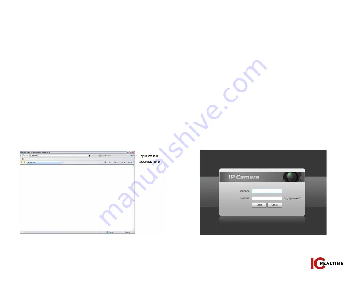
Open IE or Chrome and input the network camera address in the 

address bar. See Figure 4-1.

Figure 4-1

The login interface is shown as below. See Figure 4-2. 

Note: If it is your first time logging into the camera (and it has not 

been initialized through the ConfigTool or NVR), the camera will need 

to be initialized. A pop-up will appear to select your region. After 

selecting region, you will be prompted to create a password for the 

admin account as well as security questions in case the password is 

lost After initializing, you will be able to login to the web interface of 

the camera. 

Please input your user name and password. 


Figure 4-2

Summary of Contents for AN-IPEL-M80F-IRW1

Page 1: ... etc Please keep it away from the electromagnetic radiation object and environment Please make sure the CCD CMOS component is out of the radiation of the laser beam device Otherwise it may result in CCD CMOS optical component damage Please keep the sound ventilation Do not allow the water and other liquid falling into the camera Lightning proof device is recommended to be adopted to better prevent...

Page 2: ...tion environments The waterproof design conforms to the IP67 level It has the sound waterproof function suitable for use in the outdoor environments It can be used standalone or with a network video recorder If used standalone it is able to utilize IC Realtime s software suite including Smart ICRSS IC View and ICRSS Pro This model also supports IC Realtime s P2P connection which allows easy remote...

Page 3: ...to the Mount See Figure 2 2 Note The mount shown is for example only The mount is sold separately Figure 2 1 Figure 2 2 Figure 2 3 Figure 2 4 Step 3 Thread in the collar adapter and secure with locking screw as shown in Figure 2 3 Step 4 Thread the cabling through the collar and base Install the camera to the collar adapter and secure with set screws Installation of support cable chain is recommen...

Page 4: ...vailable in some models Locate the adjustment knobs as shown in Figure 2 5 Figure 2 5 Figure 2 6 2C Waterproofing Connectors For outdoor installations waterproofing with the included connectors is necessary See Figure 2 6 for installation steps ...

Page 5: ...will reboot when the factory reset is successful 3A OVERVIEW The IP Config tool is used to search the local network for IC Realtime devices as well as modify the IP addresses and upgrading firmware This software can be downloaded at https icrealtime com downloads under Desktop Utility Apps 3B OPERATION Double click the ConfigTools exe icon to run The interface will be displayed as shown in Figure 3 1...

Page 6: ...d the click the Initialize icon on the bottom left side and follow the process on screen to initialize the device The Operate column will allow you to modify device view device information and link to web browser See figure 3 3 Figure 3 3 To modify the device IP address select one of the devices from the list and then click the pencil icon The dialog box to modify the IP information will populate S...

Page 7: ...mand Prompt type ping network camera address to check if connection is OK or not 4B LOGIN AND LOGOUT Open IE or Chrome and input the network camera address in the address bar See Figure 4 1 Figure 4 1 The login interface is shown as below See Figure 4 2 Note If it is your first time logging into the camera and it has not been initialized through the ConfigTool or NVR the camera will need to be initi...

Page 8: ...el preview system configuration alarm and etc See Figure 4 3 Live Live video of camera Playback View recording from SD card if applicable Setting For configuration changes Alarm For monitoring alarm triggers motion detect IVS abnormalities etc Logout Logs out of the camera web GUI ...

Page 9: ...ther the main power and transformer are working normally Image is black and white Use the required power supply Check recorder compatibility with Camera video format Camera does not power on Insufficient power use the required power supply Image is not stable Poor contact on circuits Connect the cable properly Blurry image Lens glass is dirty Clean the lens Focus is in manual mode Set Focus setting...

Reviews: