background image


2

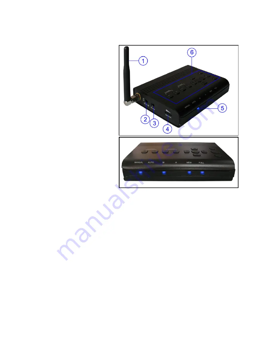
Wireless Receiver 

1. Receiver Antenna

 – receives signals from the camera(s). Adjust the antenna to vertical position for 

better signal reception. 

2. DC 9V Power Input

 – Connect the 

included DC 9V power adaptor to power 
the receiver. 

3. A/V Out Port

 – Connect the included 

A/V cable to view video on a TV or 
monitor, or record to a VCR/DVR. 

4. Alarm Volume Knob

 – Turn the knob 

to increase or decrease the volume of 
the audio alarm. 

5. Indication LEDs

 – Indicates the 

status of the system. There are 6 
indication LEDs: 

MANUAL

: Indicates manual switching 

mode between activated cameras. 

AUTO

: Indicates automatic switching 

mode between activated cameras. 

M

: Indicates manual recording mode. 

A

: Indicates auto recording mode. In this 

mode receiver starts to record when there is motion detection in camera side. 

NEW

: Indicates new recorded video. 

FULL

: Indicates that the SD card is full of memory. It is only available when Overwrite is disabled. 

6. Operation Buttons

 – Use these buttons for receiver operation. 

(Channel) M

 – Press the button to manually switch between all activated cameras. Once the button is 

pressed, the indication LED 

MANUAL

 will be on. 

(Channel) A 

– Press the button to view cameras in automatic switching mode. Once the button is 

pressed, the indication LED 

AUTO

 will be on. 

(Record) M 

– Press the button to start recording, press it again to stop recording. In this manual 

recording mode, the indication LED 

M

 will be on. 

(Record) A 

– Press the button to switch the system to automatic recording mode. In auto recording 

mode, the indication LED 

A

 will be on and the receiver starts recording when motion detected by a 

camera. The recording time can be set to 15s or 30s. Press the button again to cancel automatic 
recording.


Quad

 – Press 

Quad

 button to view the images in quad mode. Press 

Quad 

or 

(Channel) A

 buttons to 

exit from quad mode to automatic switching mode, press 

(Channel) M

 button to exit from quad to 

manual switching mode. 

Summary of Contents for CR6324

Page 1: ...DIGITAL WIRELESS CAMERA SYSTEM WITH SD CARD RECORDING INSTRUCTION MANUAL MODEL CR6324 ...

Page 2: ...ision allows for low light viewing up to 15 feet 4 5 meters Built in microphone Weatherproof for outdoor use PIR Sensor for motion detection IR illumination range of 15ft 4 5m under ideal conditions Objects at or beyond this range may be partially or completely obscured depending on the camera application Receiver Features Auto recording manual recording and schedule recording Remote control for r...

Page 3: ...ard is full of memory It is only available when Overwrite is disabled 6 Operation Buttons Use these buttons for receiver operation Channel M Press the button to manually switch between all activated cameras Once the button is pressed the indication LED MANUAL will be on Channel A Press the button to view cameras in automatic switching mode Once the button is pressed the indication LED AUTO will be...

Page 4: ... Before receiver installation choose one installation method from below 2 methods 1 Desktop or table stand For this method you only need to place the receiver on a desktop or a table 2 Hung on the screw which is fixed on a wall Decide where to hang the receiver first Make sure the range between the position and the nearest power output port is no more than 5 feet Also the range between the positio...

Page 5: ...om Controls 7 Microphone Receives sounds from the area near the camera and transmits sound from the camera to the receiver Back Controls 8 Pair Button The pair button is located on the back of the camera it is used to pair the camera with receiver Camera Installation Before you install the camera carefully plan where and how it will be positioned and where you will route the cable that connects th...

Page 6: ...em please see the pairing camera section of this manual for installation details 2 Mount the camera to the wall Mark the position of the screw holes on the wall drill holes and insert the supplied 3 plastic anchors then firmly fix the camera bracket to the plastic anchors with supplied screws 3 Adjust the viewing angle of the camera You can adjust the viewing angle to monitor desired area by rotat...

Page 7: ...e stop forward backward etc Scan Del Press the button to delete recorded files from SD card in playback interface Scan function is not available for this product Record Motion Press the button to switch the system to automatic recording mode In auto recording mode the indication LED A will be on and the receiver starts recording when motion detected by a camera The recording time can be set to 15s...

Page 8: ... When there is new recorded file the indicator will be shown on the LCD screen and flashes to alert users Meanwhile the indication LED NEW below the LCD screen will be on 5 Channel Indicator Displays the current channel number Press the Channel M button on the remote control to switch between available cameras Note To automatically switch between channels press the Channel A button on the remote c...

Page 9: ...on on the remote control the receiver starts recording Press the button again to cancel manual recording Schedule Recording Set the recording start time and end time then switch on schedule recording in the menu to enable schedule recording In this mode the receiver records at a certain time each day Playback When there is new recorded file the indication LED NEW on the receiver will be on and the...

Page 10: ...menu for system settings such as alarm volume brightness and date time setting Camera On Off Menu Select a camera by pressing the UP or DOWN button then pressing LEFT or RIGHT button to switch on or switch off the camera Press Enter button to confirm the change and exit Record Menu You can set up the recording parameters in record menu Note To use the recording function make sure a SD card is inse...

Page 11: ...ng additional cameras Use the UP or DOWN button to select the desired pairing channel and press the Enter button to begin the pairing process with a camera NOTE It is highly recommended to pair the cameras to the receiver before permanently mounting the cameras See the pairing section of this manual for details Setting Menu The Setting menu contains 6 submenus Date Time Use LEFT and RIGHT buttons ...

Page 12: ...tting all the data stored in the SD card will be deleted Note Be cautious to use this function Zoom The image can be set at original size or double size by selecting zoom x1 and zoom x 2 In double size mode press the navigation buttons to view the parts out of the screen Default Select Yes to reset the receiver to factory defaults all menu settings will be reset ...

Page 13: ...the Menu button on the receiver or remote controller Navigate to the Pairing menu option by pressing the buttons on the remote controller or on the receiver Press Enter or OK button to enter the pairing operation 4 Select a channel by pressing the UP and DOWN buttons on the remote controller or on the receiver Press Enter or OK button to confirm the selection 5 A message will be displayed on the s...

Page 14: ...Make sure that there is sound within range of the camera microphone The picture is or has become choppy The picture may become choppy when experiencing a lower frame rate i e 10 frames per second vs a higher 20 frames per second Try moving the camera closer to the receiver Remove obstructions between the receiver and camera The Picture appears to be grainy 1 For best performance use with TV Monito...

Page 15: ...ion 350mA Max Operating Temp Range 10 50 degree C Operating Humidity Range Within 85 RH Dimension 110mm x 22mm x 80mm Regulation Compliance FCC CE RoHS Compliance Yes Housing Material Aluminum Appendix 3 Camera Specifications Camera s Image Sensor Type 1 4 Color CMOS Image Sensor Effective Pixel H 640 V X 480 Image Resolution H 640 V 480 9fps H 320 V 240 25fps Lens 4 5mm F 2 0 AGC Auto AES Speed 1...

Page 16: ...on is subject to the following two conditions 1 this device may not cause harmful interference and 2 this device must accept any interference received including interference that may cause undesired operation The manufacturer is not responsible for any radio or TV interference caused by unauthorized modifications to this equipment Such modifications could void the user s authority to operate the e...

Reviews: