M0170.docx | Rev 1.2 | Modified on 20/04/2016 | © Remote Control Technologies P/L
9 | 28
OUTPUTS
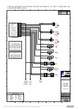
ALARM CONTROL OUTPUT
This circuit is activated as soon as an alert indicator is active. This output remains active until the EPS
control unit has no alert indicator active or the key is switched off. This output is disabled until a start signal is
sensed. This allows servicing to be carried out with the key on without the alarm sounding.
IDLE CONTROL
This circuit operates as a direct opposite to the alarm control output. It switches off when the alarm control
output is active. This output is used in conjunction with additional control systems that return the engine to
idle when an alert indicator is activated.
If return to idle is not required, this circuit should not be connected.
This circuit overrides for 10 seconds after start is activated.
ENGINE CONTROL (ETR)
This circuit operates in a similar way to the idle control output; however, it has a 0 to 40-second adjustable
time delay. This time delay is factory set to 10 seconds, allowing the machine to run for 10 seconds after an
alert indicator has been activated. This circuit is an energised to run output. This output also incorporates an
automatic system override circuit which allows the EPS control unit to override the engine oil pressure switch
allowing the engine to be started.
If shutdown is not required, this circuit should not be connected
.
WARNING!
When an alert indicator is active, special care should be taken to assess
safety considerations which may arise from shutting the machine down.
1.
Will the machine be left uncontrollable, as shutdown affects the braking
and steering of most machines?
2.
Can the machine be parked in a safe environment?


