DCN: 141-00940-02 7/14/03
23
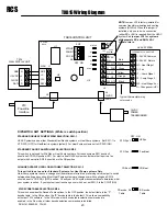
TXB16 Wiring Diagram
NOTE:
Jumper JP2 is factory installed for
common transformer heating and cooling
systems (RC=RH). When this jumper is
installed, only one red wire connection
(either RC or RH) is required from the HVAC
system.
Cut jumper JP2 for systems
with separate RC and RH 24VAC
transformers.
DIPSWITCH SW1 SETTINGS (White is switch position)
STANDARD OR HEAT PUMP SYSTEM SELECTION, SW1-1
STANDARD FAN OR FAN WITH HEAT SELECTION, SW1-2
CHANGE OVER WITH COOL OR WITH HEAT SELECTION, SW1-3
Fan/Heat
STD Fan 2
CO/Heat
CO/Cool 3
HP Sys
STD Sys 1
OFF - ON
HVAC Systems can be either Standard Gas/Electric systems or Heat Pump systems. Set SW1-1 to
STD SYS (OFF) for Gas/Electric systems (default). For Heat Pump systems set to HP SYS (ON)
This switch in not used for Std Gas or Heat Pump systems. For these systems SW1 position 2
should be STD FAN position (Off). For electric heat HVAC systems and others that require a fan
output with heat calls, SW1-2 should be in the ON position.
This sw itch in not used for Standard Systems, for Heat Pump systems Only
.
Heat Pump systems require a change over (sometimes referred to as reversing valve) output to switch
between heating and cooling. Most Heat Pump systems are change over with cooling and SW1-3
should be set to CO/COOL (OFF) position. Check your HVAC system documentation to determine what
your system requires. If your system requires change over with heat, set SW1-3 to the CO/HT (ON)
X10 DECODE TABLE SELECTION,
SW1-4
This switch overrides the Decode Table options. In the OFF position, the default table is the “P”
decode table. In the ON position, the “B” decode table is the default. This allows compatibility
with older TX15 software. In the Off mode, other decode table selection commands are
enabled, in the On mode, all other decode selection commands are inhibited.
S4
RCS
WDU
+V
GND
DATA
CLK
GND G
+12VDC +V
CLOCK C
DATA D
TS16
WALL DISPLAY UNIT
J1
STATUS
U5
U3
U1
CO C/H
STD/HP
FAN/HT
S4
SW1
1
2
3
4
OFF ON
HVAC
SYSTEM
TXB16 CONTROL UNIT
12VDC
POWER
TRANSFORMER
J4
12VDC
JACK
Typical thermostat wiring
color codes
H1
FAN
C1
C2
H2/CO
J2
X10 PLI
Red
Green
White
Yellow
Orange
G – Fan
W1 – Heat Stage 1
Y1 – Comp Stage 1
R - 24VAC Return
C - 24VAC Common
THERMOSTAT CONNECTOR
W2 – Heat Stage 2 or
O – Changeover (HP)
HVAC SYSTEM
JP2
RC=RH
HCFRX
REV G
RH
G FAN
W1 HT1
Y1 C1
W2 HT2
O CO
J5
RC
24VAC
Y2 - Comp Stage 2
Y2 C2
Black
X10
Powerline
Interface
P Decode
Table
B Decode
Table


