INSTRUCTIONS
1.
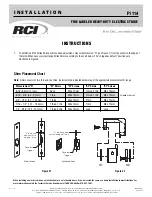
To determine if the Strike Shim positions need adjustment, measure dimension “R” (see Figure 1) from the center to the edge of
the latch. When necessary rearrange Strike Shims according to the chart below. The “shipped as default” positions are
illustrated in Figure 2.
Shim Placement Chart
Note:
Shims consist of two thin and one thick. Install with the indicated hardware per the appropriate measurement R range.
Figure #1
I N S T A L L A T I O N
®
©2007 RUTHERFORD CONTROLS INT’L CORP. WWW.RUTHERFORDCONTROLS.COM
USA: 2697 INTERNATIONAL PARKWAY, PKWY 5, VIRGINIA BEACH, VA 23452 • CANADA: 210 SHEARSON CRESCENT, CAMBRIDGE, ON N1T 1J6
PHONE • 1.800.265.6630 • 519.621.7651 • FAX: 1.800.482.9795 • 519.621.7939 • E-MAIL: [email protected]
When installing an electric strike on an inactive door of a set of double doors, it can be treated the same as a frame installation in most situations. For
more information contact the Technical Service Department at 1-800-265-6630 or 519-621-7651.
FIRE LABELED HEAVY-DUTY ELECTRIC STRIKE
F1114
ISF1114
PCN070031
R11/07DA
Figure #2
Measurement "R"
"S1" Shims
"S1" Screws
"S2" Shims
"S2" Screws
5/16" (8.2mm) or Less
None
M4 x 10mm
1 thick, 2 thin
M4 x 10mm
5/16" - 3/8", (8.2 - 9.7mm)
1 thin
M4 x 10mm
1 thick, 1 thin
M4 x 10mm
3/8" - 7/16", (9.7 - 10.7mm)
1 thick
M4 x 10mm
2 thin
M4 x 10mm
7/16" - 1/2", (10.7 - 12.2mm)
1 thick, 1 thin
M4 x 14mm
1 thin
M4 x 10mm
1/2" - 9/16" (12.2 - 13.7mm)
1 thick, 2 thin
M4 x 14mm
none
none
S1
S2
Shipped as Default
“R” distance
from center to
edge of latch
“R” distance from
center to edge of latch
Deadlock
Trigger
Deadlock
Trigger
Mortise Lock
Cylindrical Lock


