Copyright © 2015 Robot Circuits, LLC
1
RCAT-1A Rev A3 Designer’s manual
Serious Power for the Serious Designer
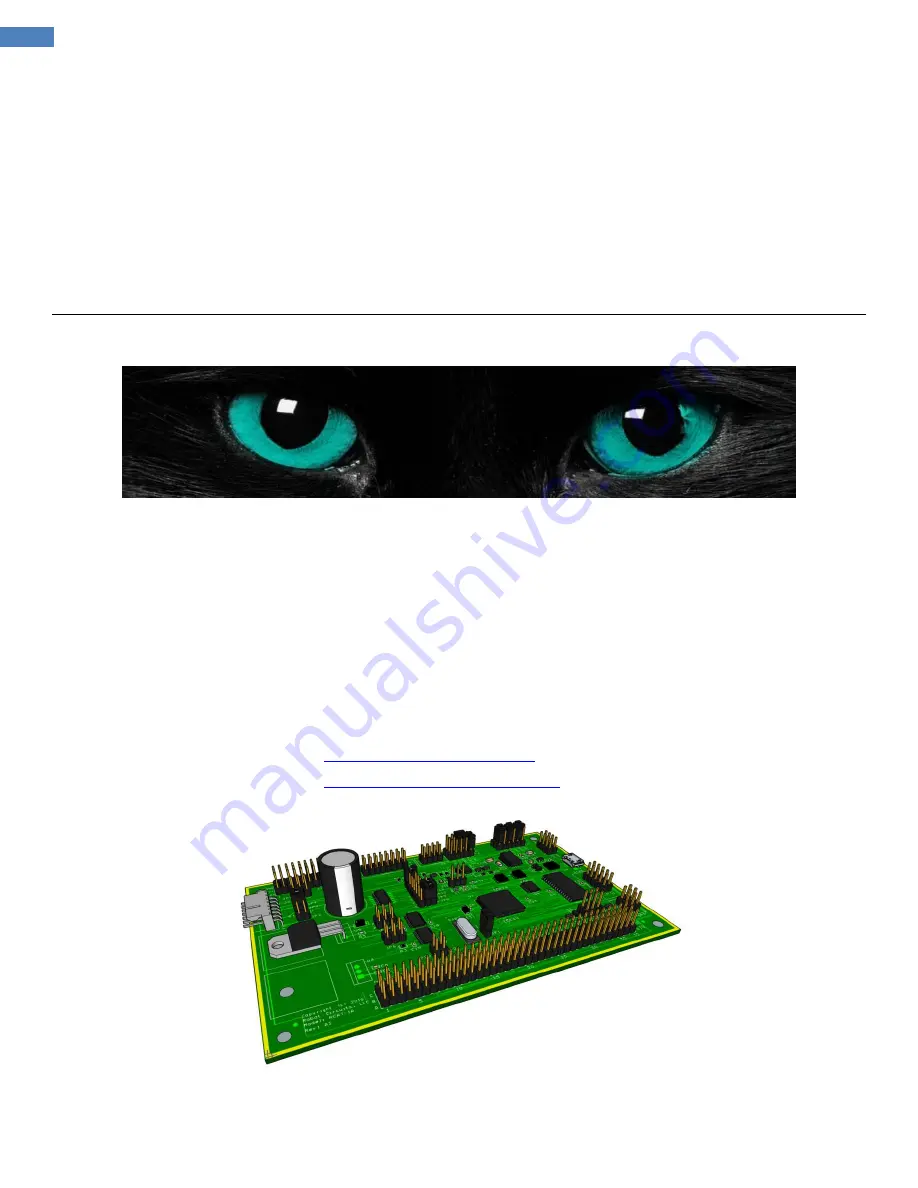
RCAT
Robotic System Control Board
Serious Power for the Serious Designer
System designer’s manual
Current Version: RCAT-1A Revision A3
Robot Circuits, LLC
[email protected]
[email protected]


