background image

Copyright © 2015 RCA Communications Systems

RPX6500  P25 MOBILE RADIO - USER MANUAL

24

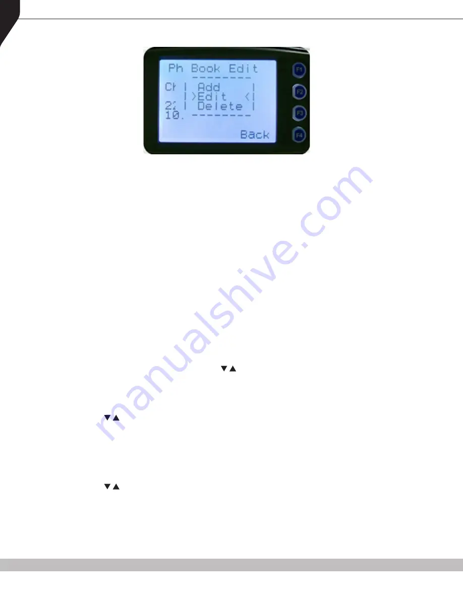
The pop-up menu items are:

• 

Add

 - Used to add a new phonebook entry.

• 

Edit

 - Used to edit (modify) the selected phonebook entry.

• 

Delete 

- Used to delete the currently selected phonebook entry.

Note.
The operations of adding a new phonebook entry and editing an existing entry are very similar 
and carried out in several steps to ensure that all the required details are entered correctly. 
Details to be entered include: Entry Type; System ID; Wide Area Coverage Network ID (WACN 
ID); Unit ID; Internet Protocol (IP) Address; and Name.

To return to the Menu screen, press either the 

Back

 key or 

Menu

 key.

A function key (when configured for 

Reset

, or any other key configured for 

Reset

) will exit back 

to the default channel screen.

5.6.1.  PHONEBOOK EDIT – TO DELETE AN ENTRY

From the ‘

Ph Book Edit

’ screen, use the  /  keys to scroll through and select the phonebook 

entry to be deleted.

Press the 

OK

 key and the ‘

Ph Book Edit

’ pop-up menu will be displayed.

Use the  /  keys to select 

Delete

 and then press 

OK

 to delete the Entry and exit back to the 

default screen.

5.6.2.  PHONEBOOK EDIT – TO ADD A NEW ENTRY

From the ‘

Ph Book Edit

’ screen, (at any phonebook Entry), press 

OK

 and the ‘Ph Book Edit’ pop- 

up menu will be displayed.

Use the  /  keys to select 

Add 

from the pop-up menu and press 

OK

. The first of the ‘add new 

entry’ sub-menu screens will be displayed.

The first sub-menu screen is the ‘

Entry Type

’ screen.

Summary of Contents for RPX6500 Series

Page 1: ...ts RPX6500V VHF 136 MHz 174 MHz RPX6500UR UHF 335 MHz 400 MHz RPX6500U UHF 400 MHz 480 MHz RPX6500U2 UHF 440 MHz 520 MHz Communications Systems U S E R M A N U A L RPX6500 Series RPX6500 Radio Optional CTRH6500 Control Head Shown ...

Page 2: ...from RCA DISCLAIMER There are no warranties extended or granted by this document RCA accepts no responsibility for damage arising from use of the information contained in the document or of the equipment and software it describes It is the responsibility of the user to ensure that use of such information equipment and software complies with the laws rules and regulations of the applicable jurisdic...

Page 3: ...5 PHONEBOOK MENU 22 5 6 PHONEBOOK EDIT MENU 23 5 7 SETUP MENU 28 5 8 USER OPTIONS MENU 29 5 9 CONTRAST MENU 30 5 10 ALERT VOLUME MENU 30 5 11 RADIO INFO MENU 31 5 12 MODE MENU 33 5 13 RSSI MENU 33 5 14 CRYPTO KEY MENU 34 5 15 STORED CALLS MENU 35 5 16 MESSAGES MENU 37 5 17 SCAN EDIT MENU 44 5 18 NO MENU 47 6 COMMON FUNCTIONS AND FACILITIES 47 6 1 SWITCH ON SWITCH OFF 47 6 2 DEFAULT SCREEN TRUNKED ...

Page 4: ...CAN 54 7 13 SCAN EDIT 54 7 14 SCRAMBLER ANALOG 54 7 15 SKIP 54 7 16 SQUELCH P25 CONVENTIONAL 54 7 17 TALKAROUND 55 7 18 ZONE 55 7 19 UNDEFINED 55 8 ACCESSORIES 55 8 1 CONTROL HEAD MICROPHONE REPLACEMENT CTR6500 PKG 55 8 2 CONTROLLER MICROPHONE REPLACEMENT MM6500 55 8 3 KEYPAD DISPLAY HANDSET KDH6500 55 8 4 CONTROLLER MICROPHONE MM6500MCD 55 8 5 CONTROLLER MICROPHONE MM65020CM 55 8 6 EXTERNAL SPEAK...

Page 5: ...UTIONS Do NOT operate your mobile radio while driving a vehicle without a hands free kit Subject to local law Do NOT operate your radio in an explosive atmosphere unless the radio s level of IECEx is approved for use in that environment Obey the Turn Off Two way Radios signs where they are posted e g on a fueling station Do NOT touch the antenna while the radio is transmitting Do NOT operate the r...

Page 6: ...our conversation to a minimum and replace the microphone on its holder after use When it is possible to move location avoid making calls from known poor signal strength areas such as the radio systems fringe areas limit of range or from screened or shadowed areas e g an underground car park or underpass To avoid unnecessary drain on the vehicle battery keep the engine running when using the radio ...

Page 7: ... Tone Multi Frequency FCC Federal Communications Commission FM Frequency Modulation ICNIRP International Commission on Non Ionising Radiation Protection ID IDentification IEC International Electrotechnical Commission IEEE Institute of Electrical and Electronic Engineers IP Internet Protocol KID crypto Key IDentification LCD Liquid Crystal Display LED Light Emitting Diode LMR Land Mobile Radio NAC ...

Page 8: ...udspeaker NAC Network Access Code Used as a filter where multiple networks may share a common RF frequency Normal Mute Mode of Radio Receive Only signals with matching NAC will be heard P25 PMR mode using analog FM used in as a fallback mode with P25 Interopera bility requirement P25 Channel Definition consisting of Tx and Rx RF frequencies NAC and TGID P25 Conventional Non trunked digital like di...

Page 9: ...ion Cable 1 1 2 CONFIGURATION Before using your RPX6500 P25 Radio it must be configured using the P25 PS The configuration process defines and loads the radio channels signaling and user options settings so the radio will operate with your system Your RCA representative can help program your radios to meet your present and future requirements 1 3 MODES OF P25 RPX6500 OPERATION The RPX6500 P25 Radi...

Page 10: ...nnels 40 Zones 250 Channels per zone Liquid Crystal Display LCD 1 44 5mm x 2 3 8 60 3mm graphic display Eight lines of 14 characters small type Three type sizes small medium and large Context based soft menu labels Light Emitting Diode LED indicator The controls on the RPX6500 Control Head are shown below in Figure 1 Figure 1 RPX6500 Control Head Indicator LED On Off Volume Down F2 Up F1 Call F7 F...

Page 11: ... Function Key F2 Programmable Function key Default Channel Down Function Key F3 Programmable Function key Default Channel Up Function Key F4 Programmable Function key Default OK Function Key F5 Programmable Function key Default Emergency Alarm Function Key F6 Programmable Function key Located on Microphone Function Key F7 Programmable Function key Default Call Function Key F8 Programmable Function...

Page 12: ... the function buttons The soft label text is defined in the PS and can be assigned to the F1 to F4 function buttons Each soft label can be up to five characters 3 1 2 TEXT PANEL The main area of the default screen is the Text Panel which displays textual information This information contains both Persistent and Non persistent text information as follows Persistent Text e g Channel name Zone name T...

Page 13: ...Figure 4 however the number of icons that can be displayed exceeds this Therefore some icons will share the same location see Table 2 RSSI Bars is a special Icon and it is displayed on the left of the default screen when a signal is being received They indicate the signal strength of the current channel The stronger the Rx signal the more bars will be displayed Figure 3 Icon Locations Menu F1 F2 F...

Page 14: ...DIO USER MANUAL 14 Table 2 Icon Details POSITION ICONS 1 ჸ Message 2 TA Talk Around 3 Ѭ Tx Other Signal Signal Scanning 4 M N S Monitor Normal Selective 4 C Connecting Connect Fail 5 25 SC P25 Digital Encrypted Scrambler 5 T Trunking 6 Locked Keypad Individual Call ...

Page 15: ...nals from the users own network will be heard on the speaker M Monitor All P25 digital radio signals on the channel will be heard Key lock indicator All keys except PTT or any function assigned as Alarm will be disabled Press the OK key for 2 seconds to unlock all keys TA Talk Around enabled indicator When shown Talk Around is active SC Scrambler indicator analog only E Emergency mode Blinking ico...

Page 16: ...ion The Setup menu is special Setup is a subgroup that can have any of the list of menu selections assigned to it This means that the lesser used selections can be partly hidden away under the Setup subgroup but still remain accessible if desired The order and presence of the Setup subgroup selections is determined by the PS For instance Info RSSI and Contrast could be placed under Setup The User ...

Page 17: ...efault Screen Normal Channel Screen Channel Back Back Back Back Back Back Back Back Back Back Back Back Back Back Back Back Back Back Back Back Back Back OK OK OK OK OK OK OK OK OK OK OK Menu 1 Zone Select Note Example menus only shown Other Menus may be configured with the CPS Submenu Submenu Submenu Submenu Submenu Submenu Submenu Key Beeps ON OFF Backlight ON OFF Other User Menu items Mode Aler...

Page 18: ... Main Menu can be accessed from the default screen by selecting the Menu F1 button To access any of the menu options from the Main Setup or User Options Menus use the and keys to scroll through the lists until the required menu option is selected with the pointer and then press the OK button Pressing the Back key at any point will go back to the previous screen 5 1 CHANNEL SCREEN The Channel Scree...

Page 19: ... unencrypted digital P25 traffic will be heard regardless of NAC or Talk Group 5 2 ZONE MENU The Zone Screen is used for changing Zones A Zone is normally defined as a group of radio channels with a common operational role When the Zone menu option is displayed press the OK button to enter the Zone select screen Once the Zone menu appears press the and keys to choose the required zone Press the OK...

Page 20: ...p menu option displayed press the OK key to access the Setup sub menus Use the keys to scroll through sub menu options and with the Squelch menu option displayed press the OK key to access the Squelch screen For a P25 digital channel the keys can be used to select either Monitor Normal or Selective squelch mode For an analog channel the keys can be used to select either Monitor or Normal squelch m...

Page 21: ... with the correct NAC and Talk Group ID TGID or correct NAC and Unit ID An S icon indicates Selective mode 5 3 2 ANALOG OPERATION 5 3 2 1 Channel Monitor Mode When Monitor squelch is selected the radio will receive any Analog voice or P25 digital signals Digital NAC or Analog Continuous Tone Controlled Selective Squelch CTCSS is not checked An M icon on the display indicates Monitor mode 5 3 2 2 A...

Page 22: ...rect access to the Mute Adjust screen from other screens can also be programmed to one of the function keys with the PS 5 5 PHONEBOOK MENU From the main channel screen press the Menu key to enter Menu Mode Use the keys to scroll through menu options With the PhoneBook menu option displayed press the OK key to access the PhoneBook screen From the PhoneBook screen it is possible to view all of the p...

Page 23: ... 5 5 2 MAKING AN INDIVIDUAL CALL WITH CALL ALERT From the PhoneBook Screen with the required phonebook entry displayed when the OK key is pressed A Call Alert is sent to the displayed ID The called radio will sound a Call Alert 5 6 PHONEBOOK EDIT MENU The Phonebook edit screen provides a method to modify the phonebook entries New entries can be added and existing entries can be modified or removed...

Page 24: ...creen press either the Back key or Menu key A function key when configured for Reset or any other key configured for Reset will exit back to the default channel screen 5 6 1 PHONEBOOK EDIT TO DELETE AN ENTRY From the Ph Book Edit screen use the keys to scroll through and select the phonebook entry to be deleted Press the OK key and the Ph Book Edit pop up menu will be displayed Use the keys to sel...

Page 25: ...OOK EDIT TO EDIT AN EXISTING ENTRY This section is used to edit an existing phonebook entry The operation is similar to adding a new phonebook entry in previous section In this example editing a P25 Trunked ID is shown It is also possible to edit a P25 Conventional ID and a P25 Group Entry Note When editing a phonebook entry for a Conventional channel not all the steps will be required From the Ph...

Page 26: ...nd then press the OK key If the system ID does not have to be changed press the OK key The Edit WACN ID sub menu screen will be displayed 5 6 3 2 WACN ID Upon entering the Edit WACN ID screen the current Wide Area Coverage Network WACN ID of the selected phonebook entry is displayed The WACN ID entry can then be changed using the numeric digits and key as a destructive backspace If the WACN ID has...

Page 27: ...does not have to be changed press the OK key The Edit IP Addr sub menu screen will be displayed 5 6 3 4 IP Address Upon entering the Edit IP Addr screen the current IP address of the selected phonebook entry is displayed The IP address can be changed using the numeric digits and the keys to move the cursor with the function key as a destructive backspace The key is used to enter a Full stop If the...

Page 28: ... the OK key If the Name does not have to be changed press the OK key The editing of the phonebook entry is then complete The phone entry will be modified in the radio and the radio will return to the default screen 5 7 SETUP MENU The Setup sub menu screens allow the radio operator to edit modify the operation of some of the general functions of the radio From the main channel screen press the Menu...

Page 29: ...0 functions may be defined in this menu by the PS From the Setup menu use the keys to scroll through sub menus and with the User Options menu option displayed press the OK key to access the User Options screen One of the programmable functions will be displayed These functions may include Key Beeps Backlight Talk Around Analog Scrambler and Low Power Override These functions can also be assigned d...

Page 30: ...esenting the contrast setting will be shown Use the keys to adjust the contrast setting as required Press the OK key to save the changes and return to the main channel screen Press the Back or Menu key to save the changes and return to the next highest menu level 5 10 ALERT VOLUME MENU The Alert Volume screen allows the user to set the Alert Volume level in relation to the current Volume setting T...

Page 31: ... channel screen Press the Back or Menu key to save the changes and return to the next highest menu level Note A minimum Alert Level may be set by the PS to ensure that the Alerts can always be heard from the speaker 5 11 RADIO INFO MENU The Radio Info screens display information that identifies the PS File description Radio ID Serial Number Software Version and IP Address From the Setup menu use t...

Page 32: ...Date Application Upgrade Ver Date PLA Code P25 Radio Unit Trunked ID and IP Addr P25 Trunked SysID WACN GID and UID Feature Authorization Enables Encryption Status Encryption Summary External Application Memory Status The Radio Info screens are read only screens Press OK to return to the Channel Screen ...

Page 33: ...ch as APCO P25 PMR or MPT Trunking When the required mode is displayed press the OK key to select that operating mode The radio will then display the default screen for that mode Keypad shortcuts can be used to change modes from the keypad as follows PMR 60 P25 80 MPT Network 1 71 MPT Network 2 72 5 13 RSSI MENU The RSSI screen displays the received signal strength in dBm When the radio has been c...

Page 34: ...the Menu key is pressed to return to the next highest menu level or the OK key is pressed to return to the main channel screen A lower RSSI value indicates a stronger signal i e 80 dBm is a stronger signal than 100 dBm 5 14 CRYPTO KEY MENU The Crypto Key menu allows the digital channel s default transmit encryption key to be modified On an encrypted radio channel the radio will attempt to use any ...

Page 35: ... the selected channel can be changed using the keys If the selected channel is changed or the radio is switched off the channel s default encryption key will be restored Press the OK key to save the changes and return to the main channel screen Press the Back or Menu key to save the changes and return to the next highest menu level 5 15 STORED CALLS MENU The Stored Calls menu is used to display th...

Page 36: ...ult screen 5 15 1 TO CALL BACK A STORED CALL From the Stored Calls screen use the keys to scroll through and select the required stored call record from the list Press the OK key and the stored calls pop up menu will be displayed From the pop up menu use the keys to select the CALL option Press the OK key and the radio will be set to the individual calling mode with the ID of the stored call Press...

Page 37: ...dio the envelope icon will not appear on the default screen To view send or delete messages from the main channel screen press the Menu key to enter Menu Mode Use the keys to scroll through the menu options With the Messages menu option displayed press the OK key to access the Messages screen The Messages pop up menu will be displayed 5 16 1 MESSAGES POP UP MENU The Messages pop up menu selections...

Page 38: ...Menu or Back keys to return to the next highest menu screen 5 16 2 MESSAGES VIEW SCREEN Received messages both short messages and text messages can be viewed from the Messages View screen When this screen is displayed it will show the most recently received message The information displayed for each message includes the sender ID and the first two lines of the received message in text string If no...

Page 39: ...ed With the MORE option selected press the OK key to display the full message With the REPLY option selected press the OK key to display the MessagesReply pop up screen Press the Reset function key if configured to return to the default screen Press the Menu or Back key to return to the next highest menu screen 5 16 2 2 Messages View More Screen The Messages View More Screen displays the selected ...

Page 40: ...et to Individual Calling Mode for a time out period determined by your radio configuration When the radio s PTT is activated an individual voice call is sent to the message sender With the SMSG option selected press the OK key to display the short message MessagesReply screen With the TXTMSG option selected press the OK key to display the message Reply Text screen Press the Menu or Back key to ret...

Page 41: ... type text Press the relevant keypad key the appropriate number of times until the desired character or number is selected The current character position is identified by a flashing cursor Use the keys to move to the next or previous character space to be entered modified Use the key to select lower upper case letters The 0 zero key is the space key Pressing and holding the Reset key for less than...

Page 42: ...fault screen without sending a message Press the Menu or Back key to return to the Message Pop up screen When the OK key is pressed the Destination Pop up screen is shown 5 16 3 1 Text Message Screen This screen allows editing and sending a free form text message A text message can have a maximum length of 210 characters The number of characters entered is displayed in the top right hand side The ...

Page 43: ...o select the destination from the phone book ENT ID to enter the destination Unit ID CANCEL to cancel the destination selection Use the keys to select the require option With CANCEL selected press the OK key to return to the previous screen i e Short Message Screen or Edit Text Message Screen With PH BK selected press the OK key to display the Phone Entry selection screen With ENT ID selected pres...

Page 44: ...keypad The valid range of a Unit ID is 0 16 777 215 The entered digits can be deleted by using the key Press the Menu or Back key to return to the Destination Selection pop up menu screen Press the Reset function key if configured to return to the default screen display Press the OK key to send the message to the entered unit ID providing it is valid The radio will then return to the default scree...

Page 45: ...kipped if the channel is currently skipped from the scan group Use the keys to scroll through and select a channel from the scan group list Press the Menu or Back key to return to the Scan Group Edit screen Press the Reset function key if configured to return to the default screen display Press the OK key and the action selection pop up menu will be displayed The Scan Group Edit pop up menu select...

Page 46: ...hest menu screen Press the Reset function key if configured to return to the default screen 5 17 2 SCAN GROUP ADD SCREEN The Scan Group Add screen shows channels that are not members of the Scan Group The second line of the display shows the name of a channel that is not a member of the Scan Group Other channels that are not members of the scan group can be selected using the keys Press the Reset ...

Page 47: ... at which time the radio is ready for use Pressing and holding the volume knob while the radio is on will turn the radio off When a low beep is heard release the knob If the radio Power Down Timer is enabled the radio will automatically turn off after a predetermined duration of inactivity i e no keys pressed as set by the PS The radio will emit warning beeps for 10 seconds prior to switching off ...

Page 48: ...ing in Selective Mute The analog channel s receive mute setting can be altered from the Mute Adjust menu While on an Analog channel both P25 and Analog FM transmissions will be received While on a P25 channel only P25 transmissions will be received To change channels press the and keys while in the channel screen Zones can be changed from the Zone menu see Section 5 2 6 4 1 RECEIVED INDIVIDUAL CAL...

Page 49: ...from your mouth press the PTT switch and note that the Tx LED is Red Wait for a Grant tone then speak clearly across the face of the microphone in a normal conversational manner In most systems it is important to wait a short time between pressing the PTT and commencing to speak This ensures that the path is properly established and avoids lost truncated or distorted speech Use the correct operati...

Page 50: ...suming scanning or voting If a Priority Channel is assigned to Scan mode the radio will interleave a check of this channel between each normal Scan channel 6 6 1 SCAN VOTE SCREEN A Scan can be started by Pressing the function key that has been assigned the scan function by the PS Selecting a zone channel that has been assigned to automatically scan by the PS Selecting the SCAN ON option under User...

Page 51: ... encryption The encryption state of the selected channel is determined by the radio configuration An encrypted channel will display the encryption icon A radio channel that has been programmed for encryption will receive either clear or encrypted traffic A transmission on this channel will be encrypted When on an encrypted channel the encryption icon will not be shown if a received signal is not e...

Page 52: ...ts Functions that may be programmed to the programmable function keys Consult RCA for those functions that have been programmed in to your radio 7 1 ALARM The Alarm function key default F5 is used to put the radio into Emergency Mode Alarm is supported in Digital mode only Pressing the Alarm key causes the radio to set the emergency flag in transmit voice messaging and depending on the radio confi...

Page 53: ...one changes The RF power level is indicated by the letter L or H replacing the antenna icon when transmitting The bar graph above this icon shows one bar for low power and six bars for high power 7 7 MENU The Menu function key is used for accessing the menu system This is normally assigned to the Menu key F1 7 8 MODE This function is a short cut to the Mode menu The Mode menu is used to change rad...

Page 54: ...it menu where the members of a scan group can be added or deleted 7 14 SCRAMBLER Analog This function enables transmitted voice to be scrambled in order to prevent radios without a scrambler from listening in on the conversation This low security form of encryption is sufficient to make speech unintelligible to other casual listeners However it does not offer high level security as other radios pr...

Page 55: ...ating to the user by a double beep at the start of each PTT 7 18 ZONE This function provides a shortcut to the detailed Zone menu 7 19 UNDEFINED No function is assigned to the relevant key 8 ACCESSORIES 8 1 Control Head Microphone Replacement CTR6500 PKG Standard control head and microphone for RPX6500 radio 8 2 Controller Microphone Replacement MM6500 Standard Microphone PTT only 8 3 Keypad Displ...

Page 56: ...og on to the system The antenna is not connected Connect the antenna properly Cannot use the radio keys The crystal connector is inserted im properly or not inserted Insert the crystal connector correctly The keys may fail to function temporarily Restart the radio The radio cannot lock out This feature may malfunction temporarily Restart the radio There is no display The LCD may fail to function t...

Page 57: ...tTwo WayRadio com Authorized North American Dealer For more information visit RCACommunicationsSystems com TRANSMITTER SPECIFICATION Power Output 1 25 Watts 3 programmable levels Current Consumption 7 5 A UHF Audio Frequency Response 1 dB to 3 dB of pre emphasized 300 to 3000 Hz on 25 kHz Channel 300 to 2550 Hz on 12 5 kHz Channel Duty Cycle 1 minute transmit 4 minute receive Modulation C4FM FM Tr...

Page 58: ...les and Service Outlet RCA Communications Systems will be responsible for all charges in returning the product to the end user via standard ground shipping service RCA Communications Systems shall have no obligation to repair or replace the product if there is damage as a result of normal wear and tear or if the damage is caused in whole or in part by catastrophe fault or negligence of the user im...

Page 59: ...e expressed written permission from RCA Communications Systems The end user of any two way radio is solely responsible for obtaining any license or other authorizations required by the Federal Communications Commission FCC For further information visit www fcc gov or call 1 888 CALL FCC 1 888 225 5322 APPENDIX A ALERT TONES AND MESSAGES Key Beep Grant Tone Error Tone Beep Alert Bip Alert 2 x Bip A...

Page 60: ...mproperly can cause biological damage Very high levels of x rays for example can damage tissues and genetic material Experts in science engineering medicine health and industry work with organizations to develop standards for exposure to RF energy These standards provide recommended levels of RF exposure for both workers and the general public These recommended RF exposure levels include substanti...

Page 61: ...ccupational controlled environment exposure limits always adhere to the following procedures GUIDELINES User awareness instructions should accompany the device when transferred to other users Do not use this device if the operational requirements described herein are not met INSTRUCTIONS Transmit no more than the rated duty factor of 50 of the time To transmit talk press the Press To Talk PTT butt...

Page 62: ...i gain 29 5 inches 75 cm Rated Power of Vehicle installed Mobile Two way Radio Recommended Minimum Lateral Distance from Transmitting Antenna 25 Watts with λ 4 dipole 2 14 dBi gain 13 5 inches 34 cm Table 4 a Rated Power and Recommended Lateral Distance for General Population Uncon trolled Exposure for RPX6500V 135 174 MHz Table 4 b Rated Power and Recommended Lateral Distance for Occupational Con...

Page 63: ...nna Install the antenna at the center of the roof or the center of the trunk deck taking into account the bystander exposure conditions of backseat passengers and recommended minimum lateral distances in Tables 4 a and 5 a These mobile antenna installation guidelines are limited to metal body motor vehicles or vehicles with appropriate ground planes The antenna installation must be in accordance w...

Page 64: ...les Warranty and Customer Support please contact Discount Two Way Radio Corporation North American RCA Distributor 1430 240th Street Harbor City CA 90710 Phone 310 224 5100 Fax 310 224 5101 www discounttwo wayradio com 2015 RCA Communications Systems All rights reserved www rcacommunicationssystems com Communications Systems ...

Reviews: