Using the example of a DVD player:
1. Connect your cable and/or antenna as described on page 5.
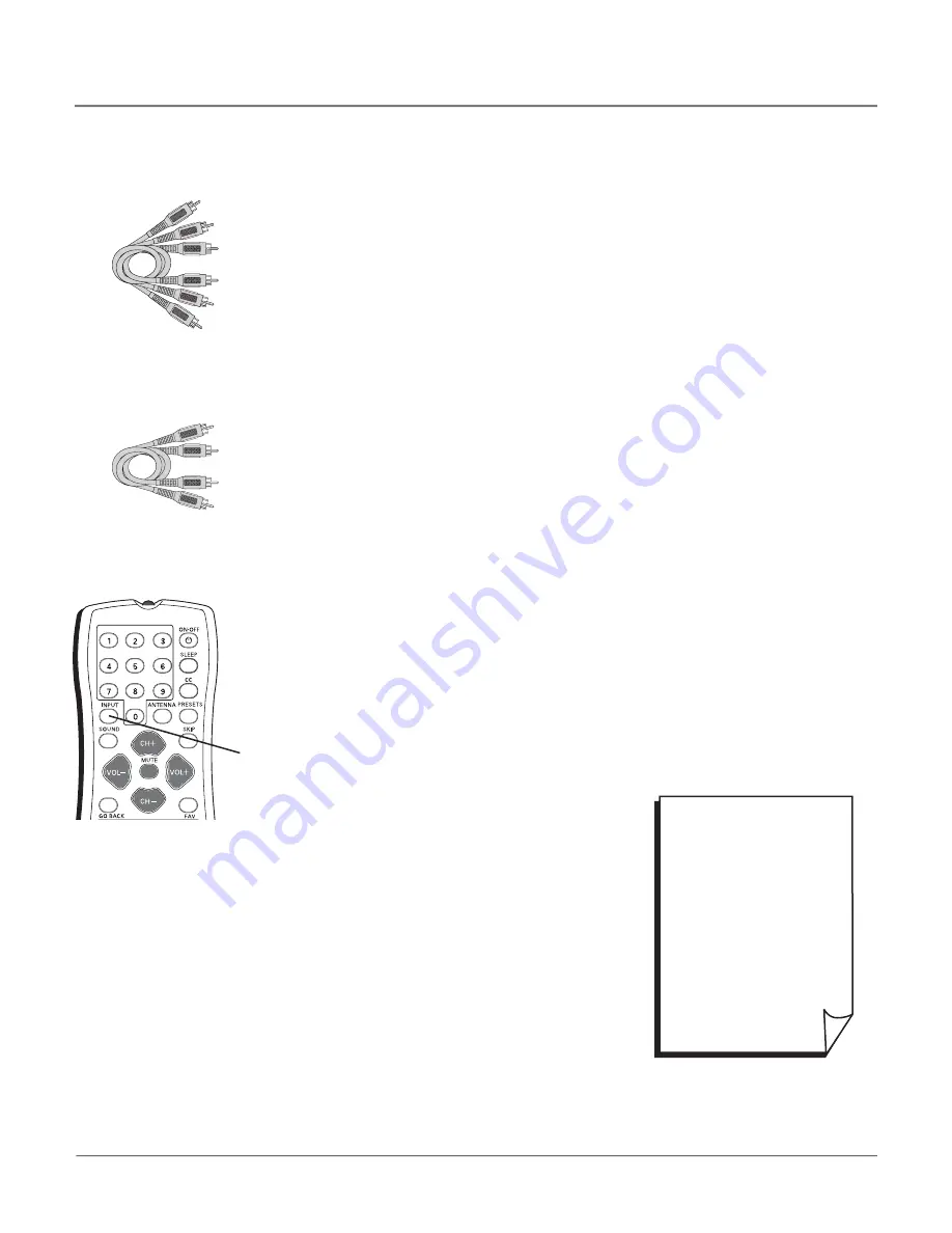
2. Connect your Y Pb Pr component video cables.
Connect three video grade cables to the Y Pb Pr jacks on the back of the TV and
to the Y Pb Pr outputs on the DVD player. Y Pb Pr cables are colored green, blue
and red. Just match the colors on the cables to the Y Pb Pr jacks.
3. Connect your audio cables.
Connect the audio (white and red) cables to the AUDIO R and L (VIDEO IN input)
jacks on the back of the TV and to the audio output jacks on the DVD player. Just
match the colors.
Important
- Y Pb Pr cables can only be used with the audio jacks from the VIDEO IN
input located on the back of the TV. You cannot use any other audio input jacks on
this TV for this connection.
4. Add a VCR to this connection.
Connect a coaxial cable to the ANTENNA/CABLE DIGITAL INPUT or ANTENNA/
CABLE ANALOG INPUT (choose one) on your TV to the Antenna Output jack on
your VCR (sometimes labeled OUT TO TV). For more details about the antenna
jacks go to page 5.
Note:
If your VCR has Audio/Video output jacks, you can connect your TV to
the VCR using audio/video cables for better quality.
Viewing the Picture from the Connected Device
The device in this example, a DVD player, is connected to the TV’s Y Pb Pr jacks. To
view the DVD player:
1. Turn on the TV and the DVD player.
2. Press the INPUT button on the remote control to toggle through the Video Input
Channels until you see
CVID1
displayed in the channel banner.
Component Video
cables (Y Pb Pr) are
color coded- Green,
Blue and Red
Audio cables are color
coded- Red= right audio;
white= left audio
INPUT
button
• To review other
connections, go to the next
page.
• If you are done connecting
devices to your TV, go to
page 13 to complete the
Initial Setup.
• If you want more details of
the jacks on your TV, go to
page 17.
Chapter 1
9
Connections & Setup


