RBI Torus WB1250 Installation And Operation Instructions Manual Download Page 27

27

Cast Iron Condensing Boilers – Installation Manual

Torus Stainless Steel Condensing Boilers & Water Heaters – Installation Manual

Whenever the gas supply piping is pressure tested the 
boiler gas controls must be protected. If the test pressure 
is equal to, or less than 

1/2 psig3.5 kPa isolate the boiler 

by closing its' manual shut off valve, see Figure 17. If the 
test pressure is greater than, or equal to 

1/2 psig3.5 kPa

disconnect the boiler and its individual shut-off valve.

ELECTRICAL WIRING

Electrical Power Connections

  Label all wires prior to disconnection when 

servicing controls. Wiring errors can cause 
improper and dangerous operation! Verify 
proper operation after servicing.


  ATTENTION. Au moment de l'entretien des 

com-mandes, étiquetez tous les fils avant de les 
débrancher. Des erreurs de câblage peuvent 
entraîner un fonctionnement inadéquat et 
dangereux. S'assurer que l'appareil fonctionne 
adéquatement une fois l'entretirn terminé.

The electrical connections to this boiler/water heater must 
be made in accordance with all applicable local codes and 
the latest revision of the National Electrical Code, ANSI /
NFPA-70. Installation should also conform with CSA C22.1 
Canadian Electrical Code Part I if installed in Canada. A 
separate circuit breaker must be installed  per boiler - (if 
required, the optional local pump FLA must be 
incorporated and sized accordingly). A properly rated shut-
off switch should be located at the boiler. The boiler must 
be grounded in accordance with the authority having 
jurisdiction, or if none, the latest revision of the National 
Electrical Code, ANSI/NFPA-70.

Line voltage field wiring of any controls or other devices must 
use copper conductors with a minimum size of #14 awg. 

Refer to point of connection diagram in back of this manual 
and the wiring diagram supplied with the boiler for proper 
wiring connections.

  A minimum of (3 in WC) and maximum of  

(14 in WC) must be maintained to the inlet of 
the boiler/water heater gas train not to exceed 
a maximum of (1 in WC) drop when firing from 
minimum input to full load of the gas supply 
line and all the appliances running.

  Always use a wrench on the gas valve body 

when making gas connections to it. Never 
over-tighten the piping entering the gas 
valve body or gas valve failure may result!

Safe lighting and other performance criteria were met 
with the gas manifold and control assembly provided 
on the boiler/water heater. All gas connections MUST 
be leak tested before putting the boiler into operation.

 Never use an open flame to test for 

gas leaks. Always use an approved leak 
detection method. Failure to comply with 
this warning can cause extensive property 
damage, severe personal injury or death!

  Gas train must be isolated when purging the 

gas line prior to commissioning the boiler.


 Corruption of the gas train components  with 

debris and cutting oils can reduce reliable 
operation which can have a negative effect 
on the operation & manufacturers warranty 
of the Dungs gas valve. The factory supplied 
Dungs MBC modulation gas valve, see Figure 
17, incorporates an internal filter that must be 
inspected and changed at required intervals. 
Reference the Dungs MBC Installation 
Instructions - 264541 for detailed instructions. 
Combined with clean gas pipes and good 
plumbing practices (such as installing a drip 
leg), should adequately protect the MBC 
valve seat, regulator and internal orifices from 
clogging or damage. However, site conditions 
might warrant an additional filter. This should 
be installed upstream of the appliance gas 
regulator to the unit.

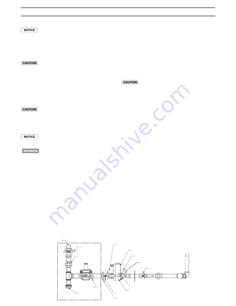
Figure 17 - Gas Supply Piping

MAIN GAS

VALVE

PRESSURE

REGULATOR

SUPPLIED BY OTHERS

SEDIMENT TRAP

AND DRIP LEG

FROM GAS SUPPLY

GROUND

UNION

FIRING VALVE

DUNGS

VALVE

MANUAL SHUT-OFF

VALVE

LOW GAS PRESSURE SWITCH

(ON APPLICABLE MODELS)

HIGH GAS PRESSURE SWITCH

(ON APPLICABLE MODELS)

SUPPLY PRESSURE TEST PORT

RIOM-0312_A

LOW FIRE GAS PRESSURE ADJUSTMENT

CSD-1 TEST PORTS

HIGH FIRE GAS PRESSURE ADJUSTMENT

Summary of Contents for Torus WB1250

Page 1: ...ntial property damage The boiler can only be operated with a dust free air supply Follow the instruction manual procedures to duct air to the boiler air intake If the boiler has been contaminatedbyope...

Page 2: ...DE SECTION IV FOR A MAXIMUM ALLOWABLE WORKING PRESSURE OF 160 PSI 1103 kPa WATER INSTALLER THESE INSTRUCTIONS TO BE AFFIXED ADJACENT TO THE BOILER WATER HEATER CONSUMER RETAIN THESE INSTRUCTIONS FOR F...

Page 3: ...heater The Torus may be installed directly on combustible flooring but never on carpeting 4 Locate the boiler water heater in an area that will prevent water damage to adjacent construction should a...

Page 4: ...led in a confined space without the intake air option two permanent openings communicating directly with or by ducts to the outdoors or spaces that freely communicate with the outdoors must be present...

Page 5: ...iler Appropriate thimbles and fire stops must be used where required Improper installation of common positive pressure vent systems can result in excessive levels of carbon monoxide which can cause se...

Page 6: ...orizontal vent runs exceed 5 ft 1 5m they must be supported at 3 ft 0 98 m intervals with overhead hangers If any part of a single wall metal vent system passes through an unheated space it must be in...

Page 7: ...ations must be made using approved fire stops The top of a vertical vent system must extend at least 51 2 ft 1 8 m above the roof surface that it passes through 4 ft 1 3 m above the intake air cap see...

Page 8: ...SAUK HM 12AC HM 12DSDA 12FCSLCA Model Size Heatfab Saf T Vent Security Chimneys Secure Seal Jeremias RBI Transition Adapter Flue Transition Adapter Flue Transition Adapter Flue Exhaust Termination 125...

Page 9: ...UNAK 08R EVD UNAK 08R 2500 3000 C10VLSL M 2SVSAFNS10 ESW UNAK 10R EVD UNAK 10R 4000 C12VLSL M 2SVSAFNS12 ESW UNAK 12R EVD UNAK 12R Factory Installed The RBI Torus is supplied with a factory installed...

Page 10: ...d for barometric dampers the barometric dampers may be omitted When required by applicable codes install a thermal spill switch on each barometric damper 1 Connect each boiler water heater riser to th...

Page 11: ...teel Condensing Boilers Water Heaters Installation Manual Figure 2 Horizontal Air Intake and Venting for a Single Direct Vent System Figure 3 Horizontal Air Intake and Venting for Multiple Direct Vent...

Page 12: ...ilers Water Heaters Installation Manual Figure 4 Vertical Air Intake and Venting for Direct Vent System Figure 5 Combination Direct Vent Systems 10 FT 3 1 m 4 FT 1 2 m 5 FT 1 5 m 1 5 FT 0 5 m 5 1 2 FT...

Page 13: ...the COMBUSTION AIR VENTILATION SECTION must be followed The vent guidelines under the HORIZONTAL DIRECT VENT SYSTEMS section must also be followed Figure 6 Side Wall Venting VERTICAL VENT Recommended...

Page 14: ...Optional NEGATIVE PRESSURE CATEGORY II The Torus is listed as a Category II appliance when vented vertically into a listed metal AL294C S S chimney system Figure 8 The chimney system must provide a n...

Page 15: ...b timent et toutes les portes entre l espace o les appareils toujours raccord s du syst me d vacuation sont install s et les autres espaces du b timent Mettre en marche les s cheuses tous les apparei...

Page 16: ...ance of 2 ft 61 cm from the center line of the terminal E Clearance to unventilated soffit F Clearance to outside corner G Clearance to inside corner H Clearance to each side of center line extended a...

Page 17: ...10 000 Btuh 3 kW and 100 000 Btuh 30 kW 36 in 91 cm for appliances 100 000 Btuh 30 kW 4 ft 1 2 m below or to side of opening 1 ft 300 mm above opening C Clearance to permanently closed window D Verti...

Page 18: ...a porch deck or balcony is fully open on a minimum of two sides beneath the floor NOTES 1 In accordance with the current CSA B149 1 Natural Gas and Propane Installation Code 2 In accordance with the c...

Page 19: ...ions are not recommended in areas where the danger of snow blockage exists Do not place the boiler water heater in a location that would subject it to runoff from adjacent buildings or damage may occu...

Page 20: ...r mixture suitable for the minimum temperature that the unit will be exposed to must be used The pump must be capable of producing a minimum of 15 more flow and overcoming a 20 increase in head loss D...

Page 21: ...6 2 4 5 13 5 4000 156 1 9 8 4 7 14 0 130 1 8 2 3 7 10 9 HEATING SYSTEM PIPING General Piping Requirements All heating system piping must be installed by a qualified technician in accordance with the l...

Page 22: ...result in damage to the heat exchanger Products such as DOWFROST DOWTHERM UCARTHERM or an equivalent product must be used to ensure proper protection to the boiler The water used for dilution of conce...

Page 23: ...T A MINIMUM OF 12 FROM PRIMARY LOOP TEE WM WM For Heat net Operation A Sensor Is Required And Installed At A Minimum Of 12 From Primary Loop Tee Riom 0205_a Tangential Type Air Separator Aquastat Heat...

Page 24: ...f water born bacteria Water Chemistry The required temperature rise across the primary heat exchanger is based on water having a hardness between 4 and 12 grains per gallon with a level of dissolved s...

Page 25: ...WATER HARDNESS AND PH AT JOB SITE THIS MUST BE MEASURED BEFORE SELECTING PUMP 5 COMMON PIPING MUST BE SIZED FOR MAXIMUM COMBINED HEATER FLOW 6 HOT WATER TANKS SHOULD BE EQUIPPED WITH A COMBINATION TE...

Page 26: ...Table 9 should be used to ensure that the gas supply piping is sized properly If more than one appliance is supplied by the same supply pipe the piping must be sized based on the maximum possible dema...

Page 27: ...WC must be maintained to the inlet of the boiler water heater gas train not to exceed a maximum of 1 in WC drop when firing from minimum input to full load of the gas supply line and all the appliance...

Page 28: ...g system piping Close the make up water valve and check and clean the strainers and make up water pressure reducing valve Open the make up water valve and adjust the system pressure if necessary The s...

Page 29: ...the front of the boiler to on It will light up when the power is on If all interlocks are properly closed the display will say Standby Figure 18 13 Slide the HeatNet controls low fire switch on the H...

Page 30: ...board is in the CAL position While in Standby no call for heat on inputs the Max percentage may be preset before firing the boiler Press the Adjust button under the Maximum setting and set this value...

Page 31: ...t the minimum input setting for 3 seconds then operates at demand input See the calibration section in the Torus Series Control IOM to enter the calibration menus NO DEMAND Post Purge 1 The main gas v...

Page 32: ...90 1 00 20 0 50 0 60 0 50 0 40 0 35 0 40 Firing Rate 1250 1500 2000 2500 3000 4000 Delta P W C Delta P W C Delta P W C Delta P W C Delta P W C Delta P W C 100 11 5 15 7 10 9 10 3 13 3 12 6 33 1 00 1 1...

Page 33: ...imit in the Limit String to Ignition Control Have We received the BLOWER signal CALL FOR HEAT PRE_PURGE Interlocks OK Are we below the Temp Band YES fire the boiler NO Send 120 VAC BLOWER signal Limit...

Page 34: ...T FLOW Indicates that inadequate flow is present LWCO LOCKOUT Indicates low or no water in the boiler Ignition Safety To test the ignition safety shutoff device close the manual shutoff valve 1 Figure...

Page 35: ...ons of this manual for reference 1 Check the operating controls for proper operation 2 The probe on a probe low water cut off must be removed cleaned and inspected at least once a year Ensure that the...

Page 36: ...anual Figure 21 Pressure Switches TO FILTER BOX BLOWER PROVE SWITCH BLOCKED FLUE SWITCH TO FLUE COLLAR TAP PS2 OPEN BLOCKED INLET SWITCH OPEN FILTER BOX TO FILTER BOX TO FILTER BOX L P GAS VALVE ELECT...

Page 37: ...OW PROVE 1 2 3 4 5 6 7 8 Low Fire Hold Fires the boiler at the minimum rate while in Calibrate This functions exactly as the T1 input Calibrate Allows adjustment of the Minimum Fire Maximum Fire and P...

Page 38: ...ers Installation Manual Figure 24 Exploded View and Replacement Parts RIOM 0319_A 9 10 13 15 14 17 16 18 20 21 22 19 23 24 11 12 23 RIOM 0319_A 25 27 27 56 49 48 41 39 38 36 55 33 33 33 33 35 26 26 37...

Page 39: ...tainless Steel Condensing Boilers Water Heaters Installation Manual 1 5 6 7 8 4B RIOM 0319_A 3 2A 2 4 4A REPLACEMENT BURNER FRONT DOOR GASKET 57 58 59 61 63 62 62 63 60 FRONT DOOR 65 66 67 71 72 72 64...

Page 40: ...78 79 80 75 MBC 1000 VALVE GAS TRAIN 80 78 76 74 73 75 77 79 MBC 2500 VALVE GAS TRAIN MBC 4000 VALVE GAS TRAIN 81 82 83 84 81 82 83 84 81 83 84 82 SUPPLY HEADER 1250 2000 COMPONENT PLACEMENT SUPPLY H...

Page 41: ...Manual 1250 TO 1500 FILTER BOX COMPONENTS 85 90 98 91 92 86 87 88 89 93 94 95 96 2000 FILTER BOX COMPONENTS 97 93 89 92 91 90 88 87 85 86 98 4000 FILTER BOX COMPONENTS 98 85 87 88 99 90 89 92 89 97 9...

Page 42: ...ing Boilers Water Heaters Installation Manual 112 113 111 110 107 106 105 108 109 114 001 ASSEMBLY ELECTRICAL PANEL WB WW1250 TO 1500 SHOWN 104 105 99 100 103 102 101 001 ASSEMBLY ELECTRICAL PANEL WB...

Page 43: ...003 1 75 0502 004 1 1 75 0502 005 1 19 Return Header Boiler 74 1009 001 1 1 1 74 1009 002 1 1 1 19 Return Header Water Heater 74 1019 001 1 1 1 74 1019 002 1 1 1 20 Rear Supply Return Jacket Panel 75...

Page 44: ...0 50 50 57 Blower to HX Casting 01 0214 001 1 1 1 01 0214 002 1 1 1 60 Coupling 2 1 2 53 6401 005 2 2 2 Coupling 4 53 6401 007 2 2 2 61 Condensate Piping Assembly 75 0546 001 1 1 1 75 0546 002 1 1 1 6...

Page 45: ...495 001 1 1 1 09 0495 002 1 1 1 98 Grommet Plate Gasket 06 0219 001 1 1 1 1 1 1 Grommet Plate NG 03 4712 001 1 1 1 1 1 03 4712 002 1 Grommet NG 06 0072 1 1 1 1 1 06 0073 1 99 Gas Inlet Manifold Assemb...

Page 46: ...ent Operation 2 Perform pre start up checks and set up follow section Operating Instructions Steps 1 10 3 Disable any external call for heat and toggle the remote local switch to REMOTE 4 Ignition and...

Page 47: ...GUARD LOW WATER CUT OFF HIGH LIMITS COMMISSIONING THE BOILER UNIT CYCLED MINIMUM OF 15 TIMES THE DELTA T BETWEEN THE HEATER IN LET AND OUTLET IS CRITICAL TO PROP ER FLOW BEFORE YOU LEAVE THE JOB SITE...

Page 48: ...uire a larger circulating pump and temperature rise Water hardness greater than 15 grains per gallon will require a water softener system See Installation Instructions for proper pump performance Exce...

Reviews: