


21
Cast Iron Condensing Boilers – Installation Manual
Torus Stainless Steel Condensing Boilers & Water Heaters – Installation Manual
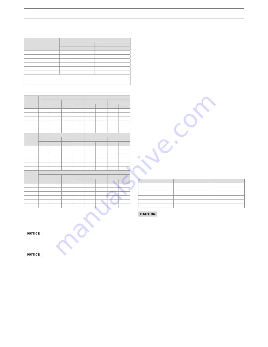
Table 6 - Temperature Rise Table
Table 6a - Temperature Rise Table
Min/Max flow correspond to a (10°F/60°F) ∆t at full input, for applications
requiring operation above and/or below these parameters, please consult
manufacturer. *Recommended (Delta T) temperature rise.
In order to maintain boiler capacity, increase
flow rates approximately (10%) and pump
head (25%) for mixtures up to 50% glycol.
Use the following equation to determine the
boiler derate capacity when adjustments aren't
made. (2012 ASHRAE Systems Handbook)
qw = 500*Q*(p/pw)*Cp*
Δ
T
Where
qw = Total heat transfer rate, BTU/h Q = flow rate, gpm
p = fluid density. lb/ft³
pw = density of water at 60°F, lb/ft³
Cp = specific heat of fluid, Btu/lb °F
Δ
T = temperature difference, °F
Model
Size
Water Flow Rates (GPM)
Full/Min Input
Full Input
Min (gpm) *
Max (gpm)*
1250
40.2
241.3
1500
48.3
289.6
2000
64.3
386.0
2500
79.1
474.5
3000
97.5
585.2
4000
130.1
780.3
*For applications requiring operation above and/or below these
parameters, please consult manufacturer.
Model
10 Deg f (Delta t)
20 Deg f (Delta t)*
(gpm)
Drop (ft)
(gpm)
Drop (ft)
GPM
L/s
Ft
kPa
GPM
L/s
Ft
kPa
1250
241.3
15.2
62.9
188.2 120.7
7.6
15.4
45.9
1500
289.6
18.3
58.0
173.4 144.8
9.1
16.4
49.0
2000
386.0
24.4
70.4
210.5 193.0
12.2
20.1
60.1
2500
474.5
29.9
43.2
129.1 237.3
15.0
15.5
46.5
3000
585.2
36.9
60.0
179.2 292.6
18.5
21.0
62.7
4000
780.3
49.2
69.7
208.3 390.2
24.6
19.9
59.6
Model
30 Deg f (Delta t)*
40 Deg f (Delta t)*
(gpm)
Drop (ft)
(gpm)
Drop (ft)
GPM
L/s
Ft
kPa
GPM
L/s
Ft
kPa
1250
80.4
5.1
7.3
21.7
60.3
3.8
4.7
13.9
1500
96.5
6.1
8.1
24.2
72.4
4.6
5.0
14.9
2000
128.7
8.1
9.9
29.7
96.5
6.1
6.1
18.2
2500
158.2
10.0
8.8
26.4
118.6
7.5
5.9
17.7
3000
195.1
12.3
11.8
35.3
146.3
9.2
7.9
23.7
4000
260.1
16.4
10.1
30.2
195.1
12.3
6.5
19.3
Model
50 Deg f (Delta t)
60 Deg f (Delta t)
(gpm)
Drop (ft)
(gpm)
Drop (ft)
GPM
L/s
Ft
kPa
GPM
L/s
Ft
kPa
1250
48.3
3.0
3.6
10.7
40.2
2.5
3.0
9.1
1500
57.9
3.7
3.5
10.4
48.3
3.0
2.6
7.8
2000
77.2
4.9
4.2
12.5
64.3
4.1
3.1
9.2
2500
94.9
6.0
4.4
13.0
79.1
5.0
3.4
10.0
3000
117.0
7.4
5.8
17.4
97.5
6.2
4.5
13.5
4000
156.1
9.8
4.7
14.0
130.1
8.2
3.7
10.9
HEATING SYSTEM PIPING
General Piping Requirements
All heating system piping must be installed by a qualified
technician in accordance with the latest revision of the
ANSI/ASME Boiler and Pressure Vessel Code, Section IV.
Where required, the piping must comply with ANSI/
ASME CSD-1, Standard for Controls and Safety
Devices for Automatically Fired Boilers.
All applicable local codes and ordinances must also be
followed. A minimum clearance of
1in, 25 mm must be
maintained between heating system pipes and all
combustible construction. All heating system piping must
be supported by suitable hangers, not the boiler. The
thermal expansion of the system must be considered
when supporting the system. A minimum system
pressure of
20 psig, 138 kPa must be maintained at
boiler operating conditions. For glycol systems, a
minimum system pressure of
30 psig, 207 kPa must be
maintained at boiler operating conditions.
Boiler /Water Heater Piping Connections
The supply and return connections should be sized to
suit the system, see Table 7.
Table 7 - Supply & Return Pipe Connection
System Cleaning & Flushing: Prior to
commissioning the boiler(s), the piping/
system must be cleaned and flushed to
prevent contaminants from settling back
into the boiler and fouling the heat
exchanger.
Isolate the boiler from the system prior to the
cleaning process. Fill the system with water,
add the cleaning solution and follow the
solution manufacturer’s instructions. Once
clean, refill the system with clean water as
specified in the Water Treatment section.
Water Treatment
This boiler was designed to operate in a closed loop
heating system. System fill water must not contain more
than 500 ppm Total Dissolved Solids, less than 150 ppm
chloride concentration and no greater than 200 ppm
Water Hardness. Suspended solids such as Magnetite,
Iron Oxides must be flushed from the system prior to
commissioning the boiler(s). The PH level must be within
the 6.5-8.5 range. Where required, the system must be
protected by the addition of a corrosion inhibitor per the
chemical supplier’s instructions.
Model Size
Supply Size
Return Size
1250
2 1/2" NPT
2 1/2" NPT
1500
2 1/2" NPT
2 1/2" NPT
2000
2 1/2" NPT
2 1/2" NPT
2500
4" NPT
4" NPT
3000
4" NPT
4" NPT
4000
4" NPT
4" NPT


