FUTERA FUSION INSTALLATION AND OPERATION INSTRUCTIONS
23
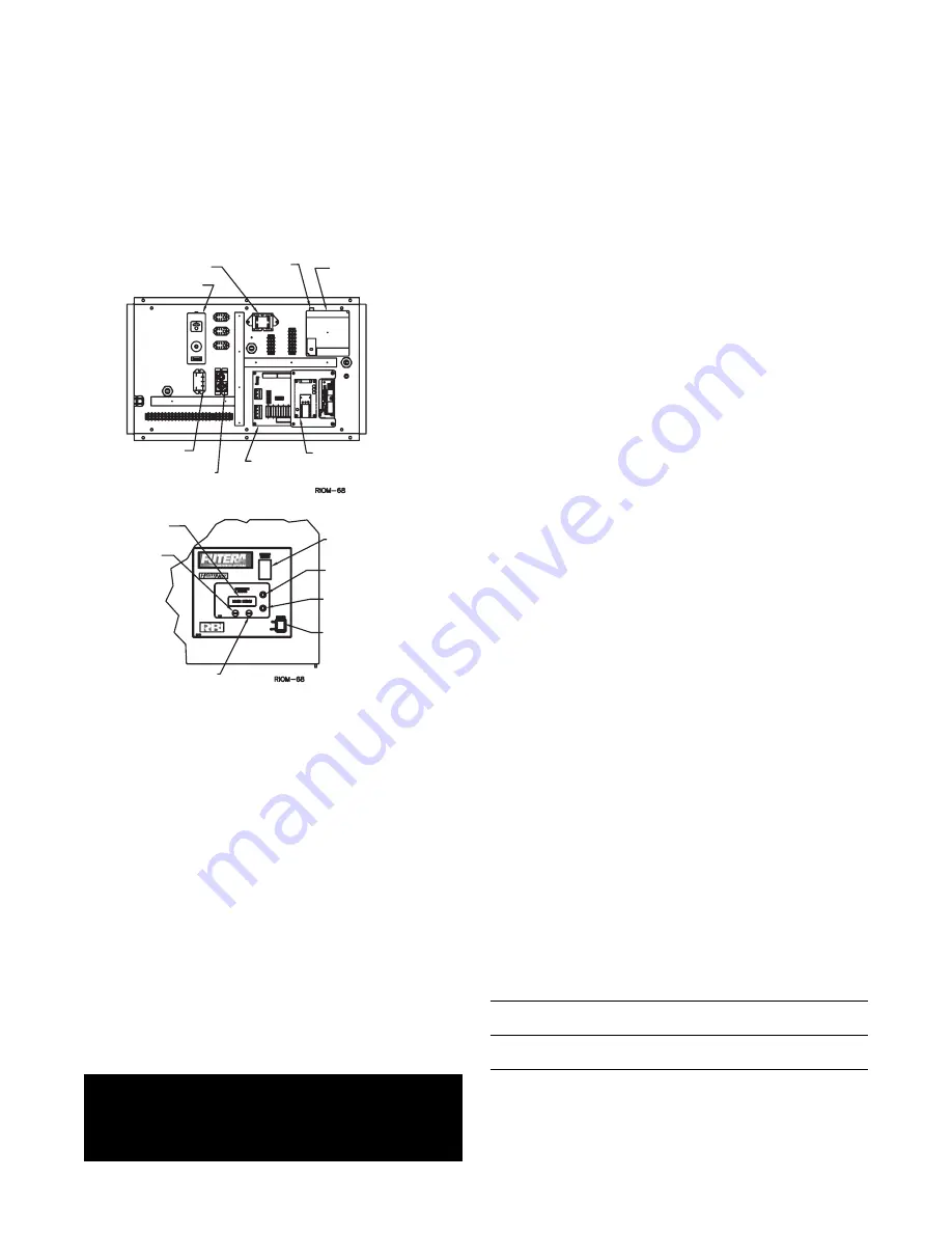
MANUAL RESET
PUMP MOTOR
RELAY
TRANSFORMER
FLAME
SAFEGUARD
MODULE
HEAT NET
CONTROL
BOARD
PROTOCESSOR
MODULE
(OPTIONAL)
LOCAL REMOTE
SWITCH
TEST RUN
SWITCH
POWER SWITCH
IGNITION STATUS
WINDOW
SELECT BUTTON
BACK
BUTTON
DISPLAY
WINDOW
UP BUTTON
DOWN BUTTON
15. Adjust the pilot pressure per the CHECKING,
ADJUSTMENT & OPERATION section.
16. Remove the demand from the 7800 control by
opening the TI terminals, allowing the boiler to stop.
Figure 15 - HeatNet Control Panel
17. Close main isolation gas valve (fi eld supplied), Figure
14.
18. Remove the manometer fitting from the pilot test
port and replace the plug. Place monitor tube on to
elbow test port located down stream of main gas
valve, Figure 14.
19. Switch the Honeywell 7800 back to “run”.
20. Create a min (TI) input demand as before. The boiler
will begin the start sequence.
21. Monitor the fl ame current on the 7800. No fl ame
current should be detected and the 7800 should
lock out. If fl ame current is detected at any time up
to the 7800 locking out, the 120V wiring on the
ignition transformer must be reversed and the test
run again to insure that no fl ame is detected.
WARNING: Improper wiring of the ignition
transformer can result in an explosion causing
extensive property damage, severe personal
injury or death!
22. Open main isolation gas valve (fi eld supplied).
23. Reset the Honeywell 7800. The boiler will start and
will run at minimum input rate.
24.
Setting the low fi re:
Allow the low fi re to settle
out for a few minutes and observe the combustion
reading. Refer to “Combustion Reading” table for
proper combustion readings and elbow pressure,
Table 12.
The low fi re O
2
-CO
2
can be adjusted in the fi eld by
opening the low fi re adjustment door located on the
forward facing side of the main gas valve. Inserting
an allen wrench and rotating the allen screw clock-
wise will increase the CO
2
and lower the O
2
, rotating
counter clock-wise will decrease the CO
2
and
increase the O
2
.
DO NOT LEAVE THE BURNER IN
AN INFRARED STATE.
A few random speckles of
red are fi ne, but large concentrations of spots or
large areas of red are not. If large amounts of red
concentrations are observed, verify combustion
readings.
25. Jumper the “AA” terminals located on the HeatNet
control board. The boiler input will rise to its
maximum input, “Run 100%”, see Figure 16.
26. Allow the boiler to reach steady state and verify
supply gas pressure and check input rates as
explained in the “Gas Supply Piping” section. Also,
refer to “Combustion Reading” table for proper
combustion readings and elbow pressure, Table 12.
27. Remove jumper “AA” and allow boiler to settle into
minimum input. Observe the combustion readings
and make any fi nal adjustments. When fi nished
remove jumper on terminals “T1”, see Figure 16 and
replace test ports to normal state.
28. Boiler allows for many modes of operation and
control methods. Reference the “Control HeatNet
IOM” and the “Control-Programming Examples” for
instruction.
Table 12 - Combustion Readings
Natural Fuel
Propane Fuel
CO2 %
8.0 - 8.5 (33%)
9.4 - 9.9 (33%)
8.3 - 8.8 (100%)
9.7 - 10.3 (100%)
O2 %
6.6 - 5.8 (33%)
6.6 - 5.8 (33%)
6.2 - 5.2 (100%)
6.2 - 5.2 (100%)
*For factory set gas manifold (elbow) pressures see
label on inner cabinet door.


