background image

Building Instructions JIMMY

Page 

 van 

15

20

Finishing 

Wing and fuselage are now ready to get their final finish. Sand everything smooth, and 
round the corners of the fuselage. Do not overdo it, avoid reducing the glue areas too 
much. The simplest way to finish all surfaces and open structures is to use iron-on 
covering film. It is important to apply the covering at a low temperature setting of your 
iron to reduce initial shrinking, and only when everything is attached properly raise the 
temperature to tighten the covering and remove any wrinkles. This is especially important 
with open structures, i.e. the wing, which should be covered at low setting on top and 
bottom first, and only then raise the setting to tighten it evenly. Be careful not to introduce 
warping of the wing, but when you do you can iron those out by ”counter-warping” the 
wing by weighting one half down on the board and carefully rotate the other tip by hand, 
reheat the covering and let it cool before you release it.
It will be difficult to describe the details of iron-on covering in a few words, best is to let 
an experienced modeller show you how it’s done, or refer to the instructions of the iron-
on film supplier, e.g. Solarfilm, Oracover and others.

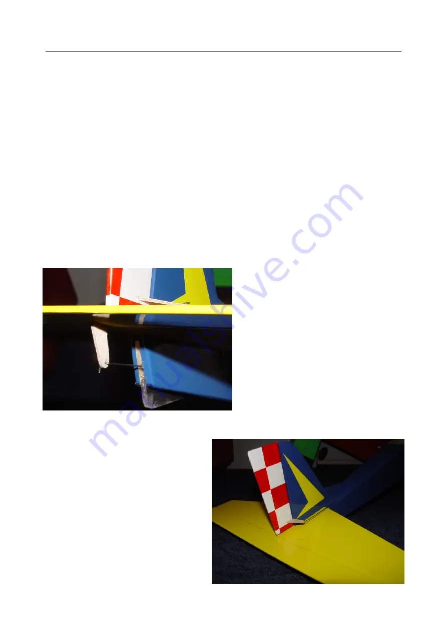
As mentioned before, the tail surfaces 
are best covered before final assembly. 
Leave the area to be glued to the 
fuselage free from covering.
Mark the position of the rudder horns, 
cut a slot and glue the horns to the 
control surfaces. Check the drawing for 
the exact positioning of the horns.

Attach the elevator to the stabiliser with 
sticky tape. Stick the tape to the top of 
the stabiliser, leaving one half past the 
edge to stick to the elevator. To ensure 
a minimum hinge gap and a maximum 
deflection angle, hold the elevator in a 
downward attitude against the rear 
edge of the stabiliser and push down 
the tape onto the elevator.
Attach the rudder in the same way, pay 
attention to the bevel on the front edge 
of the rudder.

Summary of Contents for JIMMY

Page 1: ... pins are also available To assemble plywood parts it is best to use short pin board pins which have a stout grip 4 Clothespins pegs for the same purpose You can use ordinary clothespins but they tend to leave traces on the soft balsa Purpose made little clamps are better look at the pictures to get the idea 5 Glue PVA glue is the most suitable since it will give you some time to adjust the parts ...

Page 2: ...gzags to align them Check the picture below for their orientation Lay down the bottom panel Note that the front is not square but at an angle to the right This will offset the propellor thrust direction to the right which is necessary to compensate for the air flow twist caused by the anti clockwise rotation as seen from the front of the propellor So check that the right hand edge of the bottom pa...

Page 3: ...o the rear former check the squareness again the rear former differs slightly from the picture The stabiliser support balsa and tail skid support ply parts are glued to the right hand side panel Glue the main former to the bottom panel make sure it sits square to the bottom ...

Page 4: ...re the glue sets glue the left hand side panel in place and ballast the complete assembly with a weight of your choice The bottom picture shows the tail end glued together don t do this as yet as this will be explained in detail in the next steps An old iron as shown in this picture of another model under construction is perfect ...

Page 5: ...of 5 20 Mark the center of the two formers with a vertical pencil line and line them up by sighting the two pencil lines and glue the side panels together ensuring their symmetry by aligning the stabiliser support slot with those lines ...

Page 6: ... from glue any excess should be removed with a matchstick or similar to enable sliding in the L G legs from below Use the mounting cross included with your motor to establish the correct position of the self tapping mounting screws Center the cross over the hole in the middle of the firewall mark the mounting holes and pre drill the holes with an appropriate size drill Screw the cross in place tem...

Page 7: ... cable through the top accounting for the 1 5 mm top planking of the fuselage still to be fitted The front end should protrude some 10 15 mm through the holes in the rear former Check the drawing for the exact routing of the cables and glue everything in place It is important to run the rudder cable in such a way that the steel inner cable only needs a minimum of bending on its way to the rudder c...

Page 8: ... Glue two 50x8x2 mm pine pieces to the fuselage bottom on either side of the removable landing gear To adjust their position temporarily slide the L G legs into their mounting holes with the wires against each other apply glue to the pine parts position them close to the L G wires and slide these against the wires while the glue is still wet Remove the legs carefully without moving the pine parts ...

Page 9: ...awing there Fix the 6x6 mm lower spar to the building board with pins Accurately cut a piece of 1 5 mm balsa to size for the planking of the root part and glue it to the lower spar Fix this planking to the building board with pins The trailing edge consists of a lower and an upper part made from 1 5 mm balsa sheet Cut the lower part to size and glue it to the rear edge of the planking and fix the ...

Page 10: ...ear part An extra complication is that the first root rib has to be angled so that it matches its counterpart on the other wing half Start with the front part of rib 1 Glue it at the required angle using the 3 mm ply template provided checking alignment with the drawing by looking from above Slip a piece of 1 5 mm scrap balsa underneath to allow for the planking thickness Check the front cut out a...

Page 11: ...ition of the slanted front rib part If necessary sand a little off the end of the brace to achieve this Be sure to clamp the brace to the spars until the glue has set Glue the rear parts of the 3 mm balsa root ribs onto the bottom planking and against the dihedral brace The first rib is again angled at the same angle as the front part check with the template and at right angles to the spars Glue t...

Page 12: ...s and on the bottom trailing edge Ensure the top butts against the front of the cut outs Glue the top in place and use pins and clamps to keep it in place while the glue sets Cut and sand the last 2 planking sections to size and glue pin in place Sand the excess planking and spars off flush with the slanted first rib The other wing half should fit against this ...

Page 13: ...hape the leading edge to the correct cross section The easiest way is to mark the balsa strip with two pencil lines 2 5 mm offset from the front edge and start shaving it vertically up to these lines After that shave and sand to its final shape Sand the spars leading and trailing edges flush with the outer rib Glue the 5 mm balsa end ribs on and sand the edges to match the last rib Round off the o...

Page 14: ...cond half and fettle the joint until you have an exact fit Glue the two halves together Be sure to clamp the dihedral brace to the spars until the glue has set Glue the rear root rib parts in place Glue the top trailing edge and the 1 5 mm top planking in place To avoid any damage caused by the rubber bands that hold the wing down it is best to add two rounded pine strips at the trailing edge of t...

Page 15: ...on the board and carefully rotate the other tip by hand reheat the covering and let it cool before you release it It will be difficult to describe the details of iron on covering in a few words best is to let an experienced modeller show you how it s done or refer to the instructions of the iron on film supplier e g Solarfilm Oracover and others As mentioned before the tail surfaces are best cover...

Page 16: ...servos is integral with most ESCs if not it will have to be added separately The rudder and elevator pushrods are connected to the servo arms with cylindrical connectors into which the pushrod is clamped with a setscrew Drill the hole in the arm which is approx 10 mm from the servo center to the correct diameter usually 1 or 2 mm to receive the connector which should be free to rotate with a minim...

Page 17: ...hem in again Mount the motor permanently with all screws Do not mount the propellor as yet see the Control Adjustments chapter Use velcro to mount the battery onto the battery carrier plate This will allow to mount the battery in various positions to adjust the balancing point a k a the Center of Gravity or CG of the plane The battery carrier plate remains removable to simplify removing the batter...

Page 18: ...n be used the outer ones glued on with a dab of superglue The battery hatch has to be opened for each charge so add the 1 2 mm ply lip to the forward edge in such a way that it slides under the permanent nose cover see the drawing The hatch can be held in place with an extra small rubber band attached to the wing dowels This finalises the build of the JIMMY but before you can go flying something e...

Page 19: ...electronic trims of your transmitter a k a Sub Trims For large adjustments you will have to remove the arm by undoing the mounting screw and reposition it on the splines of the servo drive end Manually position the control surfaces until they are inline with the fin stabiliser surfaces and fasten the set screws in the pushrod connectors Check the ESC instructions how to adjust your ESC to the thro...

Page 20: ...Building Instructions JIMMY Page van 20 20 ...

Reviews: