background image

10°

Travel Direction

Travel Direction

10°

Travel Direction

Side View

Side View

Side View

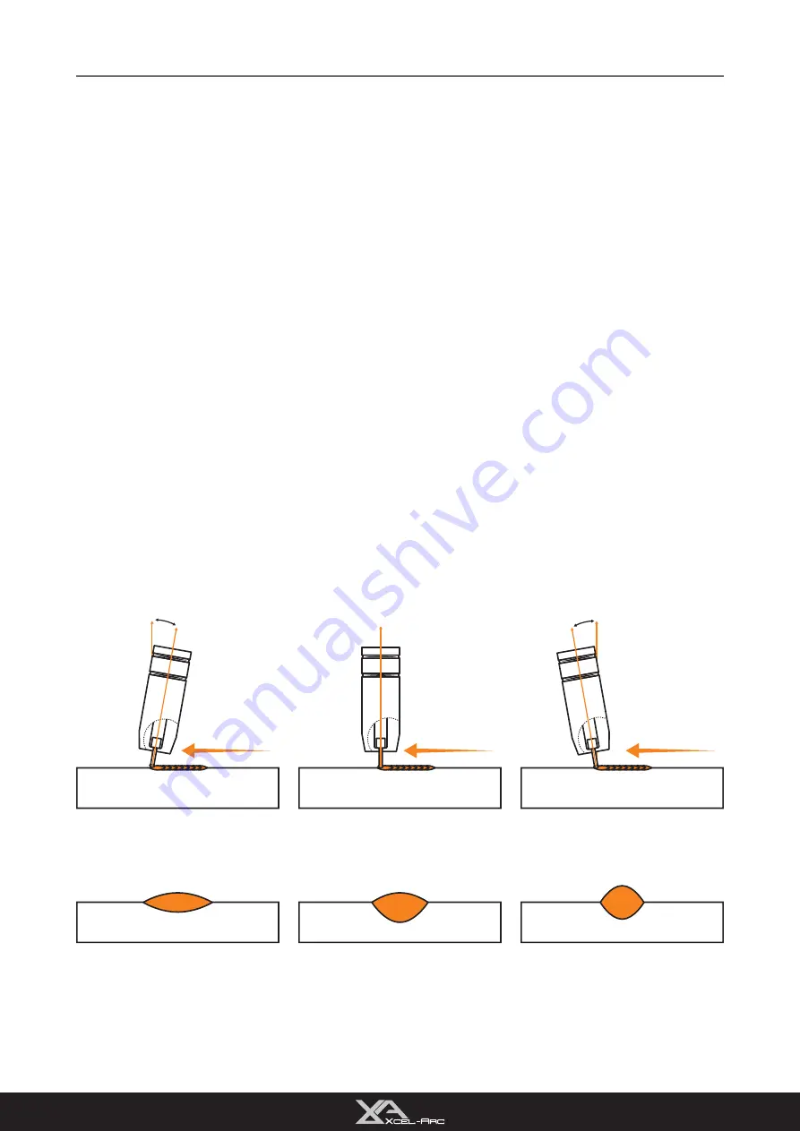
Push Technique

Flat, even weld profile, light penetration.

Narrower weld profile, even penetration.

Narrower and higher weld profile, more 

penetration.

Perpendicular Technique

Drag Technique

Basic MIG Welding

Good weld quality and weld profile depend on gun angle, the direction of travel, electrode extension (stick 

out), travel speed, the thickness of base metal, wire feed speed (amperage) and arc voltage. To follow are 

some basic guides to assist with your setup.

Gun Position - Travel Direction & Work Angle

Gun position or technique usually refers to how the wire is directed at the base metal, the angle and travel 

direction chosen. Travel speed and work angle will determine the characteristic of the weld bead profile and 

degree of weld penetration.

Push Technique

The wire is located at the leading edge of the weld pool and pushed towards the un-melted work surface. This 

technique offers a better view of the weld joint and direction of the wire into the weld joint. Push technique 

directs the heat away from the weld puddle, allowing faster travel speeds providing a flatter weld profile with 

light penetration - useful for welding thin materials. The welds are wider and flatter, allowing for minimal clean 

up / grinding time.

Perpendicular Technique

The wire is fed directly into the weld. This technique is used primarily for automated situations or when 

conditions make it necessary. The weld profile is generally higher, and deeper penetration is achieved.

Pull/Drag Technique

The gun and wire are dragged away from the weld bead. The arc and heat are concentrated on the weld pool. 

The base metal receives more heat, deeper melting, more penetration and the weld profile is higher with more 

buildup.

MIG WELDING GUIDE

32

Summary of Contents for Xcel-Arc MULTI 230 AC/DC

Page 1: ...ULTI 230 AC DC YEAR MACHINE WARRANTY 3 3 Please read and understand this instruction manual carefully before the installation and operation of this equipment Xcel Arc 2023 XA MIG230RZMTS Operating Manual ...

Page 2: ...2 ...

Page 3: ...IG WELDING GUIDE 31 SETUP FOR SPOOL GUN 36 CHANGING THE MIG TORCH LINER 40 CHANGING THE MIG TORCH LINER ALUMINIUM 42 STICK SETUP SETUP FOR STICK MMA WELDING 45 MMA STICK WELDING GUIDE 47 TIG SETUP SETUP FOR TIG 49 AC TIG WELDING GUIDE 52 DC TIG WELDING GUIDE 55 SPARES TROUBLESHOOTING MIG TORCH BREAKDOWN SPARES 60 TIG TORCH BREAKDOWN SPARES 62 MIG DRIVE ROLLERS 64 FAQ TROUBLESHOOTING 65 WARRANTY 70...

Page 4: ...ation to remove welding cutting fumes and gases In confined or heavy fume environments always wear an approved air supplied respirator Welding cutting fumes and gases can displace air and lower the oxygen level causing injury or death Be sure the breathing air is safe Do not weld cut in locations near degreasing cleaning or spraying operations The heat and rays of the arc can react with vapours to...

Page 5: ...r can explode Because gas cylinders usually are part of the welding cutting process be sure to treat them carefully CYLINDERS can explode if damaged Protect gas cylinders from excessive heat mechanical shocks physical damage slag open flames sparks and arcs Ensure cylinders are held secure and upright to prevent tipping or falling over Never allow the welding cutting electrode or earth clamp to to...

Page 6: ... to bring down the temperature inside the equipment The machine will be ready for use again when the internal temperature reaches a safe level iii Over Voltage Supply Regarding the power supply voltage range of the machine please refer to the Main parameter table This equipment is of automatic voltage compensation which enables the maintaining of the voltage range within the given range In case th...

Page 7: ...equire leaving the gas pressure in the regulator and line for an extended time period In this situation it is recommended to open the cylinder valve set the flow rate to 8 10 L min close the cylinder valve and check after a minimum of 15 minutes 5 If there is a gas loss then check all connectors and clamps for leakage by brushing or spraying with soapy water bubbles will appear at the leakage poin...

Page 8: ... 1 10mm DRIVE ROLLER SIZE 30 22 TIG SPECIFICATIONS TIG FUNCTION TYPE AC DC High Frequency TIG WELDING CURRENT RANGE 10 200A TIG DUTY CYCLE 40 C 25 200A 60 130A 100 100A 10 15A TIG WELDING THICKNESS RANGE 1 8mm STICK SPECIFICATIONS STICK WELDING CURRENT RANGE 10 200A STICK DUTY CYCLE 40 C 10 200A 60 81A 100 63A 10A 25 200A 60 130A 100 100A 15A STICK ELECTRODE RANGE 2 5 4 0mm STICK WELDING THICKNESS...

Page 9: ...utton 4 Selector Scroll Knob 5 Right Action Button 6 Output Terminal 7 Euro Connection 8 12 Pin Socket 9 Gas Outlet 10 Output Terminal Rear Panel Layout 11 On Off Switch 12 Gas Inlet 13 Power Cable Interior Layout 14 Wire Feeding Spool Holder 15 Polarity Selector 16 Geared Wire Feeder MACHINE LAYOUT 9 ...

Page 10: ...MIG230RZMTS Operating Manual RazorWeld RAZOR MULTI 230 AC DC Welder 4m 300 AMP Earth Clamp 15 AMP Plug Fitted 15 AMP to 10 AMP Conversion Lead 4m XA24 MIG Torch Twin Gauge Argon Regulator 4m T3 TIG Torch Operating Manual 4m Electrode Holder Drive Rollers XCEL G AS XCEL G AS X C E L G A S XCEL G AS XCEL G AS X C E L G A S Includes 0 8 0 9mm V GROOVE 30 22 WHAT S IN THE BOX 10 ...

Page 11: ...creen and the weld menu parameters Pressing this knob also cycles through weld cycle parameters 2 Left Action Button i hand back point right Press the Left Action Button to initiate the action in 2a ii hand back point right Press and Hold for 3s to initiate the action in 2b 3 Right Action Button i hand back point right Press the Right Action Button to initiate the action in 3a ii hand back point r...

Page 12: ...actory settings After selecting Factory Settings you will be prompted to confirm whether or not you wish to proceed with the action Machine Settings 7 Fan Change fan between Normal and Smart modes Normal Fan runs constantly Smart Fan runs only when machine requires cooling 8 Wireless Remote Connect to Wireless Foot Control To connect to a wireless foot control i Select the Wireless Foot Control op...

Page 13: ...educing the chance of sticking Hot Start Time 0 5 5s Set how long Hot Start runs for Welding Amp 10 200A Set the peak welding current Arc Force 0 100 Arc Force helps to keep the arc stabilised throughout the weld by detecting any short circuits and increasing the peak current to prevent the arc cutting out or electrode sticking DC AC Pulse Setting Values Description Peak Amp 10 200A Set the peak w...

Page 14: ...er Select the desired Torch Trigger Torch Cycle Description 2T 2T two touch means you will need to hold the trigger down on your MIG torch while you weld 4T In 4T four touch mode you will only need to press the trigger once to ignite the arc and the torch will continue to weld until you press it again to turn it off SPOT SPOT mode is consecutive and evenly timed arcs that work well if you want per...

Page 15: ...igger down on your MIG torch while you weld S2T S2T uses the same trigger logic as 2T but with added advanced weld cycle features such as Start Current and Crater Control 4T In 4T four touch mode you will only need to press the trigger once to ignite the arc and the torch will continue to weld until you press it again to turn it off S4T S4T uses the same trigger logic as 4T but with added advanced...

Page 16: ...art Start Amp Time 0 20s Set how long the Start Amp will run Welding Amp Set the peak welding current Burn Back 0 10 Set how far the wire will burn back once the torch trigger has been released Post Flow 0 20s Set how long you would like your gas to flow after the arc ends S4T Setting Values Description Pre Flow 0 20s Set how long you would like your gas to flow before the arc ignites Slow Feed 0 ...

Page 17: ...y need to click the button to ignite the arc and the torch will continue to weld until you click it again to turn it off HCT Heat Control Trigger HCT Mode lets you set a base current which you can switch to at any time during a weld by pressing the trigger button Heat Control Trigger Mode is great for manual heat input control as you go During the weld cycle push the torch trigger to switch the th...

Page 18: ...faster welding speeds better penetration a faster weld puddle on cold workpieces and allows you to weld on thicker materials FusionPlus 0 80 FusionPlus is an advanced AC TIG feature that provides greater arc focus at high welding speeds and provides deep penetration even at low AC frequencies Diameter 1 0 1 6 2 0 2 4 3 2 4 0 Optimises the welding arc ignition in AC TIG based on the chosen tungsten...

Page 19: ...OT function Diameter 1 0 1 6 2 0 2 4 3 2 4 0 Optimises the welding arc ignition in AC TIG based on the chosen tungsten diameter DC HCT Setting Values Description Pre flow 0 20s Set how long you would like your gas to flow before the arc ignites Start Amp 10 200A Set the starting current when the arc ignites Up Slope 0 20s Set how long it takes for the Start Amp to reach the Peak Amp Peak Amp 10 20...

Page 20: ...the connector then screw and tighten in place Connect the earth clamp to the positive dinse connection twist to lock in place Connect the MIG torch to the Euro connection and twist end to secure in place Connect the plug into a 15 AMP socket then switch the machine ON SETUP FOR MIG GASLESS 20 ...

Page 21: ...oller tension knob to release the wire drive 8 6 Unscrew both roller caps Ensure you have Knurled F Groove drive rollers installed If not fit correct rollers and replace the roller covers Unscrew spool retaining nut SETUP FOR MIG GASLESS 21 ...

Page 22: ...nt Burnback Adjustment Place 5kg wire spool onto the spool holder For 1kg spool see step 19 Tighten spool retaining nut Feed wire through the inlet guide tube through to the outlet guide tube Ensure that the wire passes through the roller Lift roller tension knob to lock wire in place Twist to tighten SETUP FOR MIG GASLESS 22 ...

Page 23: ...tton to feed wire through to the torch 17 Once it s fed Hold the torch trigger to feed more if needed If the wire slips or stops you will need to adjust the roller tension knob Replace front end consumables on the MIG torch Connect earth clamp to your workpiece Set weld paramaters on the digital screen See Digital Screen MIG MIG SMART SET on pages 14 16 SETUP FOR MIG GASLESS 23 ...

Page 24: ...p the torch with your workpiece then simply pull the trigger to initiate the weld For gasless MIG the drag method is recommended for optimum weld quality Release trigger to end the weld SETUP FOR MIG GASLESS 24 ...

Page 25: ...e connector then screw and tighten in place Connect the earth clamp to the negative dinse connection twist to lock in place Connect the MIG torch to the Euro connection and twist end to secure in place Connect the plug into a 15 AMP socket then switch the machine ON SETUP FOR MIG GAS SHIELDED 25 ...

Page 26: ...nsion knob to release the wire drive 6 Burnback Adjustment Unscrew both roller caps 7 Ensure you have V Groove drive rollers installed If not fit correct rollers and replace the roller covers 8 Unscrew the roller cap SETUP FOR MIG GAS SHIELDED 26 ...

Page 27: ... Burnback Adjustment Place 5kg wire spool onto the spool holder For 1kg spool see step 24 Tighten spool retaining nut Feed wire through the inlet guide tube through to the outlet guide tube Ensure that the wire passes through the roller Lift roller tension knob to lock wire in place Twist to tighten SETUP FOR MIG GAS SHIELDED 27 ...

Page 28: ... argon regulator into your gas outlet Tighten securely with wrench 15 14 To initiate the wire inching go to the screen below as your desired MIG mode Then press and hold the Right Action button to feed wire through to the torch Once it s fed Hold the torch trigger to feed more if needed If the wire slips or stops you will need to adjust the roller tension knob SETUP FOR MIG GAS SHIELDED 28 ...

Page 29: ...XCEL G AS X C E L G A S Connect gas hose to the regulator outlet and crimp in place 20 21 Adjust gas flow to 8 12L min Connect gas hose to the gas inlet on the rear of the machine Connect earth clamp to your workpiece SETUP FOR MIG GAS SHIELDED 29 ...

Page 30: ...he trigger to initiate the weld For gas shielded MIG the push method is recommended for optimum weld quality Release trigger to end the weld Set weld paramaters on the digital screen See Digital Screen MIG MIG SMART SET on pages 14 16 SETUP FOR MIG GAS SHIELDED 30 ...

Page 31: ...ead the bead separates from the end of the wire and forms a droplet that is transferred into the weld pool This process is repeated about 100 times per second making the arc appear constant to the human eye Short Circuit Short Circuit Wire Heating Wire Heating Magnetic field pinches wire Magnetic field pinches wire The wire approaches the workpiece and touches the work creating a short circuit bet...

Page 32: ... and degree of weld penetration Push Technique The wire is located at the leading edge of the weld pool and pushed towards the un melted work surface This technique offers a better view of the weld joint and direction of the wire into the weld joint Push technique directs the heat away from the weld puddle allowing faster travel speeds providing a flatter weld profile with light penetration useful...

Page 33: ...welding A travel angle of 5 15 is ideal and produces the right level of control over the weld pool A travel angle higher than 20 will give an unstable arc condition with poor weld metal transfer less penetration high levels of spatter weak gas shielding and a poor quality finished weld Work Angle The work angle is the up and down angle of the gun relative to the workpiece The correct work angle pr...

Page 34: ... unfilled groove in the base metal is created when the travel speed is too fast to allow molten metal to flow into the weld crater created by the arc heat Travel Speed Too Slow Too slow a travel speed produces a large weld with a lack of penetration and fusion The energy from the arc dwells on top of the weld pool rather than penetrating the base metal This produces a wider weld bead with more dep...

Page 35: ...parameters 2 Left Action Button i Press the Left Action Button to initiate the action in 2a ii Press and Hold for 3s to initiate the action in 2b 3 Right Action Button i Press the Right Action Button to initiate the action in 3a ii Press and Hold for 3s to initiate the action in 3b Manual MIG Setup Guide Material Type Wire Type Wire Size Drive Roller Polarity Shielding Gas Gas Flow Rate Material T...

Page 36: ...d tighten in place Connect the earth clamp to the negative dinse connection twist to lock in place Connect the Spool Gun to the Euro connection and twist end to secure in place Inset the spool gun control cable into the 9 pin socket Connect the plug into a 15 AMP socket then switch the machine ON SETUP FOR SPOOL GUN 36 ...

Page 37: ...ol onto the spool nut Feed wire through the inlet guide tube Open cover and loosen roller lock Open the wire drive Unscrew roller nut Ensure you have the correct roller for the wire size you are using If not replace with correct size Replace roller nut and tighten SETUP FOR SPOOL GUN 37 ...

Page 38: ...outlet guide tube Close wire drive and tighten roller tension knob 15 16 Remove front end consumables Push trigger to feed wire out the torch nozzle Replace front end consumables Replace spool cover and tighten 19 20 Place twin gauge argon regulator into your gas outlet Tighten securely with wrench SETUP FOR SPOOL GUN 38 ...

Page 39: ... and crimp in place Connect earth clamp to your workpiece Connect gas hose to the gas inlet on the rear of the machine 26 Set weld paramaters on the digital screen See Digital Screen MIG SMART SET on page 15 Line up the torch with your workpiece then simply pull the trigger to initiate the weld Release trigger to end the weld SETUP FOR SPOOL GUN 39 ...

Page 40: ...ll the way to exit the torch neck Remove MIG torch front end parts 2 3 Remove the liner retaining nut Carefully pull out and completely remove the existing liner Ensure MIG torch is completely unravelled until setup is complete CHANGING THE MIG TORCH LINER 40 ...

Page 41: ... torch cable assembly preventing it moving during use and ensures good wire feed Fit the liner retaining nut and screw only 1 2 way down 6 7 Snip the excess liner off about the length of the where tip holder sits past the end of the torch neck Replace the front end parts CHANGING THE MIG TORCH LINER 41 ...

Page 42: ...luminium liner Remove MIG torch front end parts 2 3 Remove the liner retaining nut Carefully pull out and completely remove the existing liner Ensure MIG torch is completely unravelled until setup is complete CHANGING THE MIG TORCH LINER ALUMINIUM 42 ...

Page 43: ...ner and neck spring through the torch then fit liner collet liner O ring and liner retaining nut 6 7 Push the liner firmly into the torch lead and tighten the liner retaining nut Loosen the inlet guide tube retaining screw CHANGING THE MIG TORCH LINER ALUMINIUM 43 ...

Page 44: ...all a U groove drive roller of the correct size for the diameter wire being used 10 11 Feed liner through Euro connection and connect and tighten the torch Take the extended aluminium liner all the way up and over the drive roller Replace the front end parts CHANGING THE MIG TORCH LINER ALUMINIUM 44 ...

Page 45: ...ion and electrode holder to the positive dinse connection For DC electrodes connect earth clamp to the positive dinse connection and electrode holder to the negative dinse connection Connect the plug into a 15 AMP socket then switch the machine ON Set weld paramaters on the digital screen See Digital Screen MMA STICK on page 13 SETUP FOR STICK MMA WELDING 45 ...

Page 46: ...ode holder Twist electrode holder to tighten and securely grip electrode Connect earth clamp to your workpiece Strike electrode against workpiece to initiate arc Drag along workpiece to weld Pull the electrode away from the workpiece to finish weld SETUP FOR STICK MMA WELDING 46 ...

Page 47: ... metal is transferred across the arc into the molten pool and becomes the deposited weld metal The deposit is covered and protected by a slag which comes from the electrode coating The arc and the immediate area are enveloped by an atmosphere of protective gas Manual Metal Arc stick electrodes have a solid metal wire core and a flux coating These electrodes are identified by the wire diameter and ...

Page 48: ...5 5 0mm 165 260 Arc Length To strike the arc the electrode should be gently scraped on the work until the arc is established An arc too long reduces penetration produces spatter and gives a rough surface finish to the weld An excessively short arc will cause sticking of the electrode and result in poor quality welds The general rule of thumb for down hand welding is to have an arc length no greate...

Page 49: ...in place Plug 9 pin torch connector in the 9 pin outlet Connect the earth clamp to the positive dinse connection twist to lock in place Connect the plug into a 15 AMP socket then switch the machine ON Connect gas hose to the gas inlet on the rear of the machine SETUP FOR TIG 49 ...

Page 50: ... G A S XCEL G AS XCEL G AS XCEL GAS Place twin gauge argon regulator into your gas outlet 6 XCEL G AS XCEL G AS X C E L G A S Tighten securely with wrench 7 Connect gas hose the the regulator outlet and crimp in place 8 Adjust gas flow to 6 10L min SETUP FOR TIG 50 ...

Page 51: ... the button on the TIG Torch IMPORTANT We strongly recommend that you check for gas leakage prior to operation of your machine We recommend that you close the cylinder valve when the machine is not in use Esseti NZ LTD authorised representatives or agents of Esseti NZ LTD will not be liable or responsible for the loss of any gas SETUP FOR TIG 51 ...

Page 52: ...Arc Narrower Weld Pool Narrower Weld Bead Faster Weld Speed Narrower Cleaning Action Current Current Slower AC Square Wave Hz Faster AC Square Wave Hz AC Square Wave Hz 20 VIPER TIG 180 AC DC Manual AC SQUARE WAVE FREQUENCY CONTROL 0342 VIPER TIG 180 ACDC Product Manual SEP19 v4 indd 20 26 09 2019 1 14 58 PM AC Square Wave Frequency Control It is possible with this machine to adjust the frequency ...

Page 53: ...ng and arc stop page These problems typically occur during the transition between and cycles The current is lesser 30 during the half of the cycle when the electrode is positive and there is a resistance of the electron flow during this half cycle rectification The lack of current flow during this half cycle makes the AC arc unstable To overcome this lack of flow during one half of the cycle a hig...

Page 54: ...dial on the welding machine More current flow from the polarity produces stronger arc energy and cur rent flow from the tungsten and is good for removing the oxidized surface of the work piece However too much current flow can drive too much energy to the tungsten causing it to overheat and melt the tungsten electrode BALANCED SQUARE WAVE FORM Balance Adjusted for More Oxide Cleansing Action Hotte...

Page 55: ...e controlled melting of most metals into a weld pool TIG welding offers the user the highest amount of flexibility to weld the widest range of material thickness and types DC TIG welding is also the cleanest weld with no sparks or spatter The intensity of the arc is proportional to the current that flows from the tungsten The welder regulates the welding current to adjust the power of the arc Typi...

Page 56: ... guide start by setting the background amperage at 20 to 30 ercent of peak amperage ulse Frequency is the control of the amount of times per second Hz that the welding current switches om Peak Current to Base Current DC Pulse TIG frequency generally ranges from 20 to 300 HZ depend ng on the job application Control of the pulse frequency also determines the appearance of the weld ulse Width is the ...

Page 57: ...n will assist in creating a weld pool of the desired size Once the weld pool is established tilt the torch at about a 75 angle and move smoothly and evenly along the joint while fusing the materials together TIG Welding with Filler Wire Technique It is necessary for many situations with TIG welding to add a filler wire into the weld pool to build up weld reinforcement and create a strong weld Once...

Page 58: ...wn that ignition delay with E3 Tungsten Electrodes actually improves over time while 2 thoriated tungsten starts to deteriorate after only 25 starts At equivalent energy output E3 Tungsten Electrodes run cooler than 2 thoriated tungsten thereby extending overall tip lifetime E3 Tungsten Electrodes work well on AC or DC They can be used DC electrode positive or negative with a pointed end or balled...

Page 59: ...ead to jagged edges imperfections or poor surface finishes not visible to the eye that will contribute to weld inconsistency and weld defects Always ensure to grind the tungsten in a longitudinal direction on the grinding wheel Tungsten electrodes are manufactured with the molecular structure of the grain running lengthwise and thus grinding crosswise is grinding against the grain If electrodes ar...

Page 60: ...erflex Cable Assembly x 3m XA2603 04 Hyperflex Cable Assembly x 4m XA2603 05 Hyperflex Cable Assembly x 5m 7 XA2514 Ergo Handle Kit c w Lock Nut 8 XA2516 Medium Large Ergo Trigger 9 XA2517 Hanger Hook optional extra 10 XA2841 Cable Support 11 XA1522 Cable Terminal Male 12 XA1505 Lock Nut 13 XASCSP1 1 Gun Plug Housing Screw 14 XASC2578 S Gun Plug Housing Spare Parts Part Number Description 15 XA154...

Page 61: ...0B Insulated Liner 0 9 1 2mm wire x 5 4m Red XA2513 30B Teflon Liner 1 0 1 2mm x 3 4m for Soft wire Red XA2513 40B Teflon Liner 1 0 1 2mm x 4 4m for Soft wire Red XA2513 50B Teflon Liner 1 0 1 2mm x 5 4m for Soft wire Red XAPA0812 4 0 30 PA Liner 3m c w Brass Neck 0 8 1 2mm 4 0mm Ø For RZ VP XAPA0812 4 0 40 PA Liner 4m c w Brass Neck 0 8 1 2mm 4 0mm Ø For RZ VP XAPA1216 4 7 30 PA Liner 3m c w Bras...

Page 62: ...ATERNCL 32 Neoprene Cover Assembly x 3 2m ATERNCL 72 Neoprene Cover Assembly x 7 2m 17 ATERCO200 40 Sheath x 4m Inc Leather Cover ATERCO200 80 Sheath x 8m Inc Leather Cover 18 ATSLH26 S Cable Support Large 19 ATSLH26 C SurelokTM Housing Cover 20 ATNSLH26 H SurelokTM Housing Large 21 AT2620 4M OB Power Cable x 4m Surelok O B Rubber AT2620 8M OB Power Cable x 8m Surelok O B Rubber 22 ATNSL3550 Surel...

Page 63: ...mm 10 T3CC12 Ceramic Cup Ø19mm 12 65 0mm 3 8 32 UNEF Part Description T3CB10 Collet Body 1 0mm T3CB16 Collet Body 1 6mm T3CB24 Collet Body 2 4mm T3CB32 Collet Body 3 2mm Standard Collet Body 66 5mm 3 8 32 UNEF Part Description T3GL10 Gas Lens Collet Body 1 0mm T3GL16 Gas Lens Collet Body 1 6mm T3GL24 Gas Lens Collet Body 2 4mm T3GL32 Gas Lens Collet Body 3 2mm Gas Lens Collet Body Head Gasket Islo...

Page 64: ...hape of the wire too much tension will push the wire out of shape and cause it to catch in the contact tip Flux Cored Gasless Wire Knurled F Groove These wires are made up of a thin metal sheath that has fluxing and metal compounds layered onto it and then rolled into a cylinder to form the finished wire The wire cannot take too much pressure from the top roller as it can be crushed and deformed i...

Page 65: ...se clean dry rust free wire Do not lubricate the wire with oil grease etc Gas nozzle clogged with spatter worn or out of shape Clean or replace the gas nozzle Missing or damaged gas diffuser Replace the gas diffuser MIG torch Euro connect O ring missing or damaged Check and replace the O ring 3 Wire stubbing during welding Holding the torch too far away Bring the torch closer to the work and maint...

Page 66: ...djust the voltage setting MIG torch lead too long Small diameter wires and soft wires like aluminium don t feed well through long torch leads replace the torch with a lesser length torch MIG torch lead kinked or too sharp angle being held Remove the kink reduce the angle or bend Contact tip worn wrong size wrong type Replace the tip with correct size and type Liner worn or clogged the most common ...

Page 67: ...tungsten Incorrect gas Use pure argon gas Inadequate gas flow Set the gas flow between 6 10 L min flow rate Alumina gas nozzle too small Increase the size of the alumina gas nozzle 5 Unstable arc during DC welding Torch connected to DC Connect the torch to the DC output terminal Contaminated base metal Remove materials like paint grease oil and dirt including mill scale from base metal Tungsten is...

Page 68: ...orrect technique 5 Lack of penetration Insufficient heat input Increase the amperage or choose a larger electrode Poor welding technique Use the correct welding technique or seek assistance for the correct technique Poor joint preparation Check the joint design and fit up make sure the material is not too thick Seek assistance for the correct joint design and fit up 6 Excessive penetration Burn th...

Page 69: ...hed E09 Over Time Of Continusly Welding Let the machine cool itself down Do not turn off the machine it requires the fans to keep running to effectively cool the machine High temperature Duty cycle reached E13 Low Input Power Power outlet may be too low try another outlet If using an extension cord ensure cord has at least 2 5mm2 copper diameter Input power is too low E41 Communication Error Conta...

Page 70: ...s in question must be repaired by an authorised repair agent as appointed by this company Warranty does not cover abuse misuse accident theft general wear and tear New product will not be supplied unless ESSETI New Zealand Limited has inspected product returned for warranty and agrees to replace product Product will only be replaced if repair is not possible Please view full Warranty term and cond...

Page 71: ...NOTES 71 ...

Page 72: ...Esseti New Zealand Limited PO Box 4189 Palmerston North 4442 Phone 06 355 1103 Email sales esseti co nz www esseti co nz Xcel Arc Esseti NZ LTD 2023 New Zealand Limited ...

Reviews: