


F232048
2–1
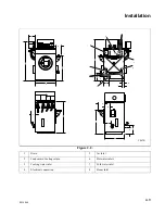
Section 2
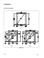
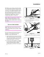
Installation
This manual is designed as a guide to the
installation and maintenance of the UY 75,
160, and 230 cabinet hardmount dye/
extractors.
Machine Overview
7KH GHVLJQ RI WKH PDFKLQH HPSKDVL]HV SHUIRU
PDQFH UHOLDELOLW\ DQG D ORQJ VHUYLFH OLIH 7KH
F\OLQGHU VKHOO DQG DOO ZHWWHG VXUIDFHV DUH IDE
ULFDWHG RI W\SH / FRUURVLRQUHVLVWDQW VWDLQ
OHVV VWHHO 7KH RXWHU SDQHOV DUH IDEULFDWHG RI
W\SH VWDLQOHVV VWHHO
7KH PDFKLQH XWLOL]HV D VLQJOH PRWRU WR GULYH WKH
F\OLQGHU YLD D 9EHOW LQ DOO VSHHGV 7KH F\OLQGHU
LV VXSSRUWHG ZLWK WZR VHDOHG EHDULQJV PRXQWHG
LQ D PDFKLQHG FDVWLURQ WUXQQLRQ ZKLFK LV EROW
HG WR D KHDY\ JDPPD VWHHO IUDPH 7KH IUDPH LV
JDOYDQL]HG DQG SDLQWHG WR SURYLGH DGGLWLRQDO
UHVLVWDQFH WR FRUURVLRQ
0DFKLQHV ZLWK WKH +H\QDX PLFURFRPSXWHU
FRQWURO KDYH SUHVHW G\H VSHHGV DQG FDQ EH UXQ
DW DQ\ VSHHG EHWZHHQ DQG 530 XVLQJ WKH
VSHHG FRQWURO NQRE RQ WKH FRQWURO SDQHO 7KH
VSHHG LV GLVSOD\HG RQ WKH GLJLWDO 530 PHWHU RQ
WKH FRQWURO SDQHO ([WUDFW VSHHG LV VHW DW *©V
IRU DOO +H\QDX FRQWUROOHG PRGHOV
0DFKLQHV ZLWK WKH 8QL'\H FRQWURO FDQ EH SUR
JUDPPHG WR RSHUDWH IURP WR 530 LQ
530 LQFUHPHQWV 3UHVHW VSHHGV DUH QRW UH
TXLUHG EHFDXVH WKH SURJUDPPHU VLPSO\ HQWHUV
WKH VSHHG WKH PDFKLQH VKRXOG UXQ ZKHQ WKH SUR
JUDP LV FUHDWHG 7KH VSHHG LV GLVSOD\HG RQ WKH
3DQHO9LHZ VFUHHQ 8QL'\H PDFKLQHV DOVR KDYH
YDULDEOH VSHHG H[WUDFWLRQ
([WUDFWLRQ VSHHG FDQ EH SURJUDPPHG WR UXQ DW
DQ\ VSHHG XS WR WKH PD[LPXP VSHHG RI WKH SDU
WLFXODU PDFKLQH LQ * LQFUHPHQWV
:DWHU LV LQMHFWHG LQWR WKH PDFKLQH WKURXJK
HOHFWULFDOO\ RSHUDWHG YDOYHV 2Q +H\QDX PRG
HOV WKH YDOYHV DUH FRQWUROOHG E\ WKH GLJLWDO ZD
WHU PHWHU ZKLFK KDV WZR FXVWRPL]DEOH ZDWHU
OHYHOV 2Q 8QL'\H PRGHOV SUHVHWV DUH QRW
QHHGHG EHFDXVH WKH SURJUDPPHU VLPSO\ HQWHUV
WKH YROXPH RI ZDWHU UHTXLUHG 7KH 8QL'\H V\V
WHP DOVR SURYLGHV OLTXRU UDWLR FRQWURO 0DQXDO
FRQWURO RI WKH ZDWHU OHYHO DW WKH PDFKLQH LV SUR
YLGHG RQ ERWK V\VWHPV
$ SQHXPDWLFDOO\ RSHUDWHG GUDLQ YDOYH LV XVHG WR
UHWDLQ WKH ZDWHU DQG G\H VROXWLRQ LQ WKH PD
FKLQH 7KH GUDLQ YDOYH LV LQVWDOOHG LQ D QRUPDO
O\ FORVHG FRQILJXUDWLRQ
7KH F\OLQGHU LV GHVLJQHG ZLWK WKUHH OLIWHUV RU
ULEV WKDW OLIW WKH JDUPHQWV IURP WKH G\H VROXWLRQ
ZKHQ WKH F\OLQGHU URWDWHV DW ORZ VSHHGV DQG DO
ORZ WKH JDUPHQWV WR WXPEOH EDFN LQWR WKH VROX
WLRQ 7KH F\OLQGHU LV SHUIRUDWHG DOORZLQJ WKH
ZDWHU WR SDVV WKURXJK DQG GUDLQ IURP ZLWKLQ
GXULQJ WKH G\H SURFHVV DQG H[WUDFWLRQ
7KH GRRUORFN V\VWHP SUHYHQWV RSHQLQJ RI WKH
VWDLQOHVV VWHHO GRRU ZKHQ ZDWHU LV LQ WKH PD
FKLQH ,W DOVR SUHYHQWV WKH PDFKLQH IURP RSHU
DWLQJ ZKHQ WKH GRRU LV RSHQ
$ OLTXRU VDPSOH YDOYH LV ORFDWHG QHDU WKH ERW
WRP RQ WKH ULJKW VLGH RI WKH PDFKLQH DV YLHZHG
IURP WKH IURQW 7KLV YDOYH LV SURYLGHG WR DOORZ
G\H VROXWLRQ VDPSOHV WR EH WDNHQ DW DQ\ WLPH


