background image

Chapter 1: Basic Operation

9

4. The display automatically returns to the previous mode if you do not press a 

button for 10 seconds.

If you press another mode button within 10 seconds you will select the associated 
mode. For example: 

auto


selects Auto mode, 

standby


selects Standby mode.

1.6 Data pages

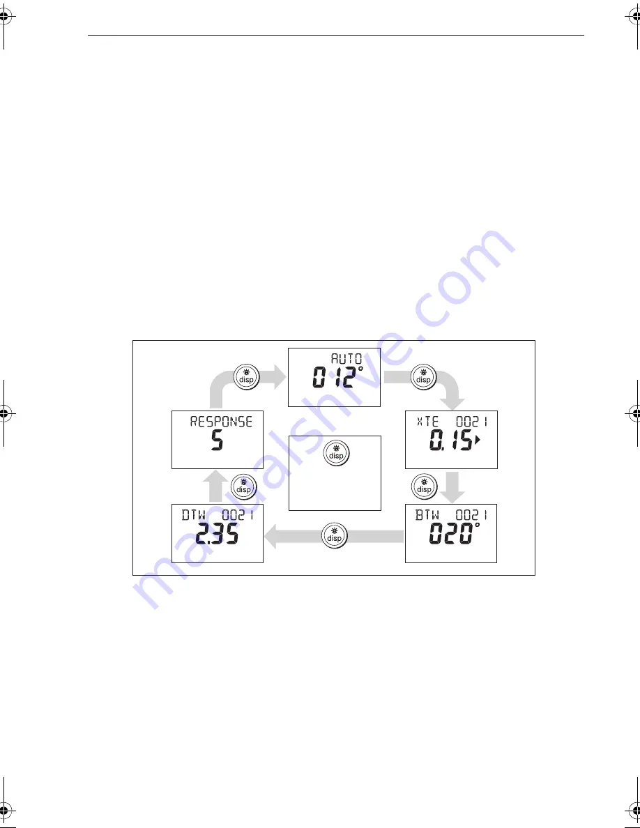
A series of data pages on the Pilot Controller enables you to quickly monitor various 
information from your SPX-5 Sport system. To access these data pages:
1. Press 

disp

 to access the first data page.

2. Press 

disp


again to cycle the next data page, then continue this process to reach 

the page you want.

3. When all pages have been displayed and you press 

disp


again, the display 

returns to the current SPX-5 Sport system mode screen (for example, 

AUTO

).

When you first use your SPX-5 Sport system, four data pages are available, as in the 
following illustration, but you can configure up to fifteen data pages during Display 
calibration, as detailed in the 

SPX-5 Sport Installation & Commissioning Guide

.


If the required information is not available for any data page, dashes are displayed.
Most data pages show repeated data so are for information only; you cannot adjust 
the values on them. An exception to this is the 

RESPONSE


page, where you can adjust 

the value using the

 -1

 and

 +1

 buttons.

Waypoint names

If waypoints have been given names, the Pilot Controller will display them on the 
Cross Track Error (

XTE

), Bearing To Waypoint (

BTW

) and Distance To Waypoint 

(

DTW

) data pages:

Waypoint names of five characters or less are displayed together with the page 
name (as shown by screen 

A

 below).

D10533-1

Autopilot mode

Data page 1

Data page 3

Data page 4

Data page 2

Default data pages

Press for 1 sec to 

return to  previous 

data page

81293_3.book  Page 9  Tuesday, August 25, 2009  7:53 AM

Summary of Contents for SmartPilot X5

Page 1: ...www raymarine com SmartPilot X5 Document reference 81293 3 Date August 2009 Sport Operating Guide...

Page 2: ...Autoadapt Auto GST AutoSeastate AutoTrim Bidata G Series HDFI LifeTag Marine Intelligence Maxiview On Board Raychart Raynav Raypilot RayTalk Raystar ST40 ST60 Seaclutter Smart Route Tridata UniControl...

Page 3: ...ring by hand 4 Using the autopilot to steer to a heading 5 Changing course in Auto mode 5 AutoTurn 5 Avoiding obstacles 5 Steering away 6 Selecting a change of course 6 Off Course alarm 6 1 4 Adjustin...

Page 4: ...rival circle 18 Route completion 18 Chapter 3 Troubleshooting Maintenance 19 3 1 Troubleshooting 19 SPX 5 Sport system alarm messages 20 3 2 Maintenance 21 Important 21 Spare parts 21 EMC Servicing an...

Page 5: ...al control in an emergency Make sure that all members of crew know how to disengage the autopilot Regularly check for other boats and any obstacles to navigation no matter how clear the sea appears a...

Page 6: ...or any differences between the product and the accompanying documents Product disposal Waste Electrical and Electronic WEEE Directive The WEEE Directive requires the recycling of waste electrical and...

Page 7: ...please take a few minutes to fill out the warranty card It is important that you complete the owner information and return the card to us to receive full warranty benefits You can also register onlin...

Page 8: ...vi SmartPilot X 5 Sport Operating Guide...

Page 9: ...ST Advanced Steering Technology AutoLearn Raymarine s self learning calibration system Extended systems You can connect the Pilot Controller to other Raymarine SeaTalk equipment so it can send and rec...

Page 10: ...system controller is on the operation of disp initiates other operating functions as described below Start up mode The SPX 5 Sport system always powers up in Standby mode with the Pilot Controller dis...

Page 11: ...nsducer The rudder position indicator can be turned on or off during display calibration see the SmartPilot X5 Sport Installation Setup Guide for details D10910 1 Distance units no units kilometres nm...

Page 12: ...he torque restraint away from the dashboard to avoid contant with any protruding objects Replacing the pin after use Inspect the Pin and R Clip for any wear or damage prior to re use Standby mode stee...

Page 13: ...ourse in Auto mode In Auto mode use 1 10 1 and 10 to change the locked heading in either 1 or 10 steps Use 1 or 10 to apply changes to port and 1 or 10 for changes to starboard For example press 10 th...

Page 14: ...ed heading Selecting a change of course 1 Use 1 10 1 and 10 to select a change of course in the appropriate direction For example press 10 three times for a 30 dodge to port 2 When you are safely clea...

Page 15: ...the SPX 5 Sport system is switched off You can also make temporary adjustments to the response level to quickly match performance to changing conditions Note however that these temporary changes to r...

Page 16: ...n and turn on the lights 2 Press disp to cycle through the possible illumination settings LAMP 3 the brightest setting LAMP 2 LAMP 1 OFF LAMP 1 LAMP 2 LAMP 3 and so on As you change the setting the il...

Page 17: ...irst use your SPX 5 Sport system four data pages are available as in the following illustration but you can configure up to fifteen data pages during Display calibration as detailed in the SPX 5 Sport...

Page 18: ...SPX 5 Sport system activates the Man Overboard alarm if it receives a man overboard MOB message from another instrument on the SeaTalk system It displays the text MOB instead of the waypoint number o...

Page 19: ...ng to waypoint and waypoint number information OFFCOURSE PT or Stb Off course alarm Occurs if the vessel has been off course from the locked heading for longer than 20 seconds PT Deviation to port Stb...

Page 20: ...how DISPLAY CAL 2 Press disp once The display will now show USER CAL 3 Press auto to enter User calibration The Response setup page is displayed 4 To access other User calibration pages press disp to...

Page 21: ...irements for Track mode To operate in Track mode the SPX 5 Sport system must receive route information from a suitable navigation system such as A SeaTalk compatible chartplotter or GPS unit An NMEA 0...

Page 22: ...than 0 3 nm from the track a Large Cross Track Error warning will sound see page 16 Leaving Track mode You can leave Track mode at any time To do this either Press auto to return to Auto mode or Pres...

Page 23: ...otter to initiate a new route to the waypoint Track keeping Cross Track Error Cross track error XTE is the distance of the vessel from the planned track An XTE can be generated if You enterTrack mode...

Page 24: ...cross track error If a cross track error of greater than 0 3 nm occurs the SPX 5 Sport system will sound a Large Cross Track Error warning and the Pilot Controller will show whether you are to the po...

Page 25: ...oint Advance the SPX 5 Sport system will maintain the current heading and continue to sound the warning To skip a waypoint SeaTalk chartplotters only If you want to advance to the next waypoint before...

Page 26: ...ve reached the last waypoint of a route in Track mode the Pilot Controller displays a ROUTE COMPLETE message if you are using a SeaTalk chartplotter or NO DATA if you are using an NMEA chartplotter Yo...

Page 27: ...ou have not calibrated the compass Carry out the devi ation and alignment procedures see SmartPilot X 5 Sport Installation Setup Guide Sport Drive getting hot Manually check that the steering system o...

Page 28: ...is can occur if the weather load on helm is too high or if the optional rudder posi tion sensor has passed beyond the preset rudder limits or rudder end stops Manually check that the steering system o...

Page 29: ...icing or replacement please contact your Raymarine authorized service agent NO DATA Caused by any of the following situations the compass is not connected the SPX 5 Sport system is in Track mode and i...

Page 30: ...Ensure all cable connectors are securely connected Examine the controller and cables for signs of wear or damage Replace any damaged components CAUTION Avoid damage when cleaning Do NOT wipe the Pilot...

Page 31: ...enance 23 Service interval Inspect and service in line with your steering system manufacturer recommendations In any event a Raymarine approved service must be carried out every 2 years or 200 engine...

Page 32: ...d Questions section and servicing information the web site gives e mail access to the Raymarine Technical Support Department and a details of the locations of Raymarine agents worldwide Telephone help...

Page 33: ...LAY CAL screen ii After another 2 seconds you see controller software version 2 Press disp to display the computer software version 3 Press disp again to display the total number of hours the SPX 5 Ti...

Page 34: ...26 SmartPilot X 5 Sport Operating Guide...

Page 35: ...th one another causing a degradation of their performance Use the EMC guidelines in this book to ensure optimum Electromagnetic Compatibility EMC between equipment and minimize any unwanted interactio...

Page 36: ...26 SmartPilot X 5 Sport Operating Guide...

Page 37: ...ning 10 Current limit alarm 20 D Data pages 9 Waypoint names 9 Display contrast 8 lighting 8 Drive stopped alarm 20 E EMC information iii 22 Emergency release pin 4 Engaging autopilot 5 F Fuse replace...

Page 38: ...etup Response level 11 Shallow Alarm 11 Standby mode 4 Switching on off 2 T Technical support 23 Tidal stream compensation 16 Track mode avoiding obstacles 14 cross track error 15 entering 14 leaving...

Reviews: