background image

5.1 General cabling guidance

Cable types and length

It is important to use cables of the appropriate type
and length

• Unless otherwise stated use only standard cables

of the correct type, supplied by Raymarine.

• Ensure that any non-Raymarine cables are of the

correct quality and gauge. For example, longer
power cable runs may require larger wire gauges
to minimize voltage drop along the run.

Routing cables

Cables must be routed correctly, to maximize
performance and prolong cable life.

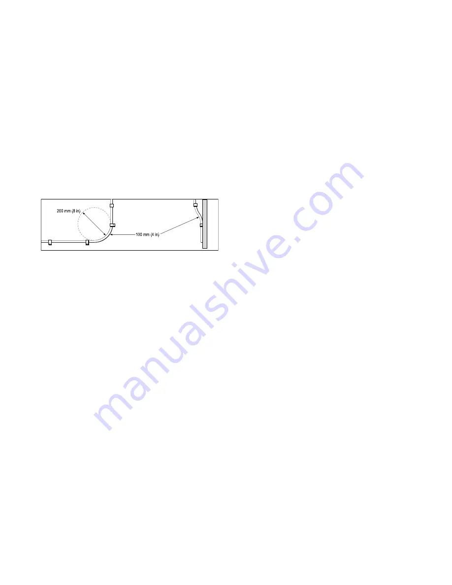
• Do NOT bend cables excessively. Wherever

possible, ensure a minimum bend diameter of 200
mm (8 in) / minimum bend radius of 100mm (4 in).

Protect all cables from physical damage and

exposure to heat. Use trunking or conduit where
possible. Do NOT run cables through bilges or
doorways, or close to moving or hot objects.

Secure cables in place using tie-wraps or lacing

twine. Coil any extra cable and tie it out of the way.

• Where a cable passes through an exposed

bulkhead or deckhead, use a suitable watertight
feed-through.

• Do NOT run cables near to engines or fluorescent

lights.

Always route data cables as far away as possible
from:

• other equipment and cables,

• high current carrying AC and DC power lines,

• antennae.

Strain relief

Ensure adequate strain relief is provided. Protect
connectors from strain and ensure they will not pull
out under extreme sea conditions.

Circuit isolation

Appropriate circuit isolation is required for
installations using both AC and DC current:

• Always use isolating transformers or a separate

power-inverter to run PC’s, processors, displays
and other sensitive electronic instruments or
devices.

• Always use an isolating transformer with Weather

FAX audio cables.

• Always use an isolated power supply when using

a 3rd party audio amplifier.

• Always use an RS232/NMEA converter with

optical isolation on the signal lines.

• Always make sure that PC’s or other sensitive

electronic devices have a dedicated power circuit.

Cable shielding

Ensure that all data cables are properly shielded
that the cable shielding is intact (e.g. hasn’t been
scraped off by being squeezed through a tight area).

Suppression ferrites

• Raymarine cables may be pre-fitted or supplied

with suppression ferrites. These are important for
correct EMC performance. If ferrites are supplied
separately to the cables (i.e. not pre-fitted), you
must fit the supplied ferrites, using the supplied
instructions.

• If a ferrite has to be removed for any purpose (e.g.

installation or maintenance), it must be replaced in
the original position before the product is used.

• Use only ferrites of the correct type, supplied by

Raymarine or its authorized dealers.

• Where an installation requires multiple ferrites to

be added to a cable, additional cable clips should
be used to prevent stress on the connectors due
to the extra weight of the cable.

34

Summary of Contents for Quantum Radome

Page 1: ...INSTALLATION INSTRUCTIONS Quantum Radar...

Page 2: ...imed trademarks of FLIR Systems Inc All other trademarks trade names or company names referenced herein are used for identification only and are the property of their respective owners This product is...

Page 3: ...passcode 16 3 3 Multifunction display compatibility 17 Compatible multifunction displays 17 Incompatible multifunction displays 17 3 4 Multifunction display software requirements 17 Software updates 1...

Page 4: ...adar scanner over RayNet 44 Powering on a Quantum Radar 44 Pairing with a Quantum Radar using Wi Fi 44 MFD access point connection when connected to Quantum Wi Fi 45 Standby and sleep modes for Wi Fi...

Page 5: ...nstall this product Do NOT connect or disconnect equipment with the power switched on unless instructed in this document Caution Power supply protection When installing this product ensure the power s...

Page 6: ...les and antennas In the case of SSB radios the distance should be increased to 7 ft 2 m More than 2m 7ft from the path of a radar beam A radar beam can normally be assumed to spread 20 degrees above a...

Page 7: ...Raymarine Incorporated could violate compliance with FCC rules and void the operator s authority to operate the equipment Technical accuracy To the best of our knowledge the information in this docume...

Page 8: ...ter 2 Document and product information Chapter contents 2 1 Document information on page 12 2 2 Parts supplied on page 13 2 3 Quantum Radome product overview on page 13 Document and product informatio...

Page 9: ...umentation for your product please Refer to the product s core model number which can be found listed on the label on the rear or underside of your product or accessed from any Raymarine multifunction...

Page 10: ...rovides a map like representation of the area around your vessel enabling you to identify other vessels buoys and land features such as coastlines and hills The Quantum Radome has the following featur...

Page 11: ...16 3 3 Multifunction display compatibility on page 17 3 4 Multifunction display software requirements on page 17 3 5 Tools required on page 18 3 6 Typical systems on page 18 3 7 Product dimensions on...

Page 12: ...electronics and requires the following additional components for full operation Compatible Raymarine multifunction display Refer to Compatible multifunction displays for a list of compatible multifun...

Page 13: ...400 3 4 Multifunction display software requirements The operation of this product requires that your Raymarine LightHouseTM powered MFD is running LightHouseTM software version 17 or later Caution Ins...

Page 14: ...from your planned installation For information on how to connect the products refer to the relevant Cables and connections section for your Quantum variant For information on available cables and acce...

Page 15: ...searchlights horns masts etc see Shadow areas and false echoes for additional information Clear of heat and fumes At least 1m 3ft from a magnetic compass or other scanners Shadow areas and false echoe...

Page 16: ...beamwidths of the 2 scanners In all cases you should aim to achieve as much physical separation as possible to minimize any potential interference 3 9 Quantum Wi Fi only installation requirements Whi...

Page 17: ...ing a location for your Quantum Radar that will be connected using a Wi Fi connection it is important to consider the effects your surroundings can have on the Wi Fi signal The Wi Fi signal will refle...

Page 18: ...mescreen Set up Wireless connection Wi Fi Wi Fi Sharing Wi Fi Name 4 Go to the location you have chosen for your Radar 5 Open the Wi Fi Analyzer app on your smart device and scan available networks 6...

Page 19: ...r is determined independently by each device manufacturer However in general the performance will be similar 1 4 Unable to maintain a connection usually accompanied by very poor connection speed Light...

Page 20: ...et Chapter contents 4 1 Wi Fi only Quantum variants on page 26 4 2 General cabling guidance on page 26 4 3 Connections overview on page 27 4 4 Power connection on page 30 4 5 Network connection on pag...

Page 21: ...damage and exposure to heat Use trunking or conduit where possible Do NOT run cables through bilges or doorways or close to moving or hot objects Secure cables in place using tie wraps or lacing twin...

Page 22: ...the extra weight of the cable 4 3 Connections overview Use the following information to help you identify the connections on your product Connector Connects to Suitable cables RayNet network or devic...

Page 23: ...plied with a RayNet cable Refer to the Chapter 2 Document and product information section for more information Refer to the 11 4 RayNet to RayNet cables and connectors section for information on suita...

Page 24: ...d with a combined power data Digital Radar cable you can use a Y adapter part number A80308 to connect the existing cable end to the scanner s connectors 1 Ensure that the vessel s power supply is swi...

Page 25: ...roducts in your system such as sonar modules can create voltage peaks at certain times which may impact the voltage available to other products during the peaks Power distribution Recommendations and...

Page 26: ...f equipment shares a breaker use individual in line fuses for each power circuit to provide the necessary protection In all cases observe the recommended breaker fuse ratings provided in the product s...

Page 27: ...e multifunction display with Wi Fi capability 2 Quantum Radome 3 Wi Fi datalink Refer to the Chapter 7 System checks and troubleshooting section and to your MFD documentation for further information a...

Page 28: ...Quantum variant with Wi Fi only Chapter contents 5 1 General cabling guidance on page 34 5 2 Power cable routing Wi Fi variant only on page 35 5 3 Power connection on page 35 Cables and connections Qu...

Page 29: ...ill not pull out under extreme sea conditions Circuit isolation Appropriate circuit isolation is required for installations using both AC and DC current Always use isolating transformers or a separate...

Page 30: ...nnection to 12V 24V power supply Power supply 4 Black cable negative Power supply s negative terminal In line fuse and thermal breaker ratings The following in line fuse and thermal breaker ratings ap...

Page 31: ...res need to be connected If the supplied power cable is NOT fitted with an inline fuse you MUST fit a suitably rated fuse or breaker between the red wire and the battery s positive terminal Refer to t...

Page 32: ...tailed in the following standards BMEA Code of Practice for Electrical and Electronic Installations in Boats NMEA 0400 Installation Standard ABYC E 11 AC DC Electrical Systems on Boats ABYC A 31 Batte...

Page 33: ...Chapter 6 Mounting Chapter contents 6 1 Mounting pre requisite breather holes on page 40 6 2 Mounting the scanner on page 40 6 3 Radar scanner protection sailing vessels on page 42 Mounting 39...

Page 34: ...e to the mounting platform ensuring that the arrow on the template is pointed towards the front of the vessel 2 Drill 3mm pilot holes in the four positions shown on the template 3 Drill out the pilot...

Page 35: ...tum Radar scanners Only 1 one Quantum Radar scanner can be used at any one time per networked system If you have more than one Quantum Radar scanner installed on your vessel and want to use them at th...

Page 36: ...unit or the bracket Raymarine strongly recommends that you check the condition and security of the bracket mounting feet the security lanyard s the Radar scanner guard and the Radar scanner unit itsel...

Page 37: ...Chapter 7 System checks and troubleshooting Chapter contents 7 1 Post installation procedures on page 44 7 2 Troubleshooting on page 46 System checks and troubleshooting 43...

Page 38: ...h also supports Wi Fi During pairing the Wi Fi credentials of all MFDs with Wi Fi switched on are sent to the Quantum Radar At subsequent power cycles the Quantum Radar will automatically connect to t...

Page 39: ...it s important to understand how these modes can potentially impact the pairing process Sleep mode If the connection to the MFD is lost while the scanner is in Standby mode the scanner will switch to...

Page 40: ...prior to packing and shipping subjected to comprehensive test and quality assurance programs However if you experience problems with the operation of your product this section will help you to diagnos...

Page 41: ...procedure described in the MFD Operations manual Multiple Quantum Radars more information Only 1 one Quantum Radar scanner can be powered at any one time per networked system It is possible to have 1...

Page 42: ...t to Possible cause Possible solutions Incorrect network credentials Ensure you are using the correct passphrase the Wi Fi network s passphrase can be found in the Wi Fi settings on the broadcasting d...

Page 43: ...Wi Fi traffic Network connection established but no data Possible cause Possible solutions Connected to the wrong network Ensure that your devices is connected to the correct network Device software i...

Page 44: ...Chapter 8 Maintenance Chapter contents 8 1 Maintenance on page 52 8 2 Unit cleaning instructions on page 52 Maintenance 51...

Page 45: ...ther maintenance tasks with the Radar powered off Ensure the antenna is firmly attached to the mounting surface Check that any connected cables are in good condition and securely attached Examine all...

Page 46: ...hapter 9 Technical support Chapter contents 9 1 Raymarine product support and servicing on page 54 9 2 Operation instructions on page 55 9 3 Viewing product information on page 55 Technical support 53...

Page 47: ...mpatible multifunction display This option displays information such as product serial number and software version With the Homescreen displayed 1 Select Set up 2 Select Maintenance 3 Select Diagnosti...

Page 48: ...Chapter 10 Technical specification Chapter contents 10 1 Technical specification on page 58 Technical specification 57...

Page 49: ...e Storage temperature range Additional storage conditions Humidity Maximum wind speed IPX6 10 C to 55 C 25 C to 70 C Store upright do not block vents on underside Up to 95 at 35 C 100kts Range scales...

Page 50: ...s 11 1 Quantum Radar accessories on page 60 11 2 Network hardware on page 60 11 3 Network cable connector types on page 61 11 4 RayNet to RayNet cables and connectors on page 62 11 5 RayNet to RJ45 ad...

Page 51: ...itable adapter cables RJ45 SeaTalkhs network switch E55058 8 port switch for network connection of multiple SeaTalkhs devices featuring RJ45 connectors RJ45 SeaTalkhs crossover coupler E55060 Enables...

Page 52: ...11 3 Network cable connector types There are 2 types of network cable connector RayNet and RJ45 SeaTalkhs RJ45 SeaTalkhs connector RayNet connector Spares and accessories 61...

Page 53: ...abling you to pull the cables through conduits and other obstacles 5 3 RayNet to RayNet right angle coupler adapter Suitable for connecting RayNet cables at 90 right angle to devices for installations...

Page 54: ...ouse MFD 1 3 Adapter cable with a RayNet male plug on one end and an RJ45 SeaTalkhs waterproof male plug on the other end Connect a legacy G Series GPM 400 C Series Widescreen or E Series Widescreen M...

Reviews: