background image

5.4 Radar check

Warning: Radar scanner safety

Before rotating the radar scanner, ensure all personnel
are clear.

Warning: Radar transmission safety

The radar scanner transmits electromagnetic energy.
Ensure all personnel are clear of the scanner when
the radar is transmitting.

Checking the radar

1. Select a Radar page.

The Radar scanners will now initialize in standby mode, this
process will take approximately 70 seconds.

2. Press the

POWER

button.

3. Press the

Radar Tx/Stdby

softkey and set to Tx.

The scanners should now be transmitting and receiving.

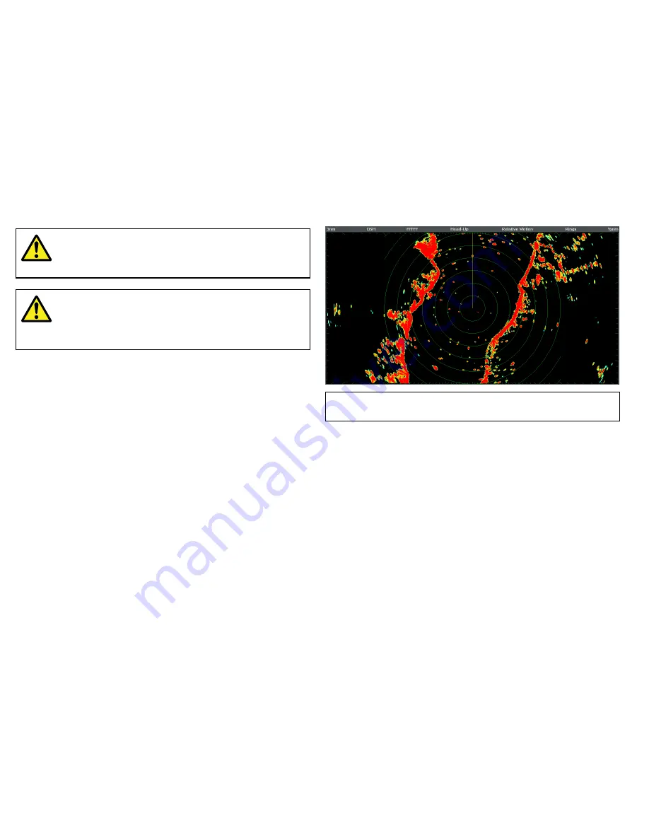
4. Check that the radar screen is operating correctly.

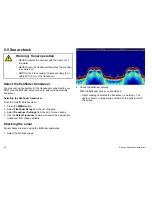
Typical HD digital radar screen

Note:

The example above is representative of the enhanced

output provided by a HD digital radar scanner.

Points to check:

• Radar sweep with echo responses are shown on screen.

• Radar status icon rotating in top right hand corner.

Check and adjust bearing alignment

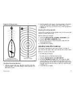
Bearing alignment

The radar bearing alignment ensures that radar objects appear at
the correct bearing relative to your boat’s bow. You should check
the bearing alignment for any new installation.

56

E-Series Widescreen installation

Summary of Contents for E90W

Page 1: ...E Series Widescreen Multifunction Display Installation instructions E90W E120W and E140W models E Series Widescreen installation...

Page 2: ......

Page 3: ...star ST40 ST60 Seaclutter Smart Route Tridata UniControl Hybridtouch and Waypoint Navigation are trademarks of Raymarine UK Limited All other product names are trademarks or registered trademarks of t...

Page 4: ......

Page 5: ...r 18 2 6 Pack contents 19 2 7 Tools 20 Chapter 3 Cables and connections 21 3 1 General cabling guidance 22 3 2 Connections overview 23 3 3 Power connection 23 3 4 SeaTalkhs network 26 3 5 NMEA 0183 co...

Page 6: ...shooting 75 6 9 SeaTalkhs LED indications 75 6 10 Miscellaneous troubleshooting 76 Chapter 7 Technical support 77 7 1 Raymarine technical support 78 7 2 3rd party support 79 Chapter 8 Technical specif...

Page 7: ...nstructions in this guide Warning Switch off power supply Ensure the boat s power supply is switched OFF before starting to install this product Do NOT connect or disconnect equipment with the power s...

Page 8: ...hart card door is firmly closed This can be confirmed by an audible click Caution Use the sun covers To protect your product against the damaging effects of ultra violet light always fit the sun cover...

Page 9: ...of such information and you are advised that errors in such information may cause the product to malfunction Raymarine is not responsible for damages or injuries caused by your use or inability to us...

Page 10: ...her equipment using a cable not supplied by Raymarine a suppression ferrite MUST always be attached to the cable near the Raymarine unit Declaration of conformity Raymarine Ltd declares that the E Ser...

Page 11: ...al accuracy To the best of our knowledge the information in this document was correct at the time it was produced However Raymarine cannot accept liability for any inaccuracies or omissions it may con...

Page 12: ...12 E Series Widescreen installation...

Page 13: ...2 1 Handbook information on page 14 2 2 Installation checklist on page 14 2 3 E Series Widescreen system on page 15 2 4 System protocols on page 17 2 5 Data master on page 18 2 6 Pack contents on page...

Page 14: ...load as PDFs from www raymarine com E Series handbooks Description Part number Installation and commissioning instructions 87116 Operating instructions quick reference 86137 User reference handbook 81...

Page 15: ...of equipment as part of your marine electronics system Basic system example D11713 1 SeaT alkhs switch E Series Widescreen display Digitalsounder DSM Autopilot Controller ST6002 Autopilot DigitalRadom...

Page 16: ...Talkng backbone SeaT alkng SeaT alkng SeaT alkng RS125 GPS Alarm Video SeaT alkhs switch Engine SeaT alkhs G Series M onitor AIS 500 Sirius Weather SR100 Antenna DigitalRadar DigitalSounder DSM Digita...

Page 17: ...urrent equipment will need to have a separate power connection SeaTalkng is a proprietary extension to NMEA 2000 and the proven CAN bus technology Compatible NMEA 2000 and SeaTalk SeaTalk2 devices can...

Page 18: ...examples are 4800 baud rate Used for general purpose communications including FastHeading data 9600 baud rate Used for Navtex 38400 baud rate Used for AIS and other high speed applications 2 5 Data m...

Page 19: ...5 1 5 m 4 9 ft Power and data cable 6 Screw pack 7 Document pack includes Multilingual CD Installation and commissioning instructions Cutting template End User License Agreement EULA 8 Micro fiber dry...

Page 20: ...d for installation D11580 1 Adhesive tape Power drill Jig saw File 5 mm 3 16 in drill bit panel mounting 35 mm 1 3 8 in hole cutter bracket mounting drill bit bracket mounting Screwdriver 20 E Series...

Page 21: ...network on page 26 3 5 NMEA 0183 connection on page 34 3 6 SeaTalk connection on page 35 3 7 Alarm connection on page 36 3 8 GPS connection on page 37 3 9 AIS connection on page 38 3 10 Fastheading c...

Page 22: ...cable passes through an exposed bulkhead or deckhead use a suitable watertight feed through Do NOT run cables near to engines or fluorescent lights Always route data cables as far away as possible fr...

Page 23: ...out 3 3 Power connection Widescreen display 19 waymulti cable Red 7Afuse Black 12 V 24 V supply Data and video D11210 2 Power distribution Raymarine recommend that all power connections are made via a...

Page 24: ...y rated conductor to the boat s common ground The preferred minimum requirement for the path to ground bonded or non bonded is via a flat tinned copper braid with a 30 A rating 1 4 inch or greater If...

Page 25: ...the figure stated here Breakers fuses and circuit protection The power cable includes an in line fuse It is recommended that you fit an additional thermal breaker or fuse at the distribution panel Di...

Page 26: ...used with E Series Widescreen to Create a network of up to 5 E Series Widescreen displays Connect a digital radar scanner Connect a digital sounder DSM Note A network containing more than a single con...

Page 27: ...5 Digital sounder e g DSM400 Radar connection The display is compatible with Raymarine digital radar scanners The scanner is connected using a SeaTalkhs cable The digital radar is usually connected v...

Page 28: ...is is only required with open array type scanners 5 Connection to power supply Radar connected directly to the display Note The connector on the free end of the radar cable does not have a locking wea...

Page 29: ...D11685 1 1 3 2 4 1 Digital radar scanner 2 Display 3 Crossover coupler 4 Connection to power supply Cables and connections 29...

Page 30: ...xtension cable connects to the radar scanner Digital radar cables You will need at least 2 cables to connect the digital radar scanner One cable connects the scanner to a SeaTalkhs switch or crossover...

Page 31: ...ires Cable Part number Notes 2 5 m 8 2 ft extension cable A92141 5 m 16 4 ft extension cable A55080 10 m 32 8 ft extension cable A55081 SeaTalkhs switch or crossover coupler to display unit SeaTalkhs...

Page 32: ...Series Widescreen display can be used with the following DSM units DSM400 DSM300 DSM30 The display can support 1 DSM module Sonar connected directly to the display On smaller systems with only one di...

Page 33: ...eaTalkhs network cable E55049 5 m 16 4 ft SeaTalkhs network cable E55050 10 m 32 8 ft SeaTalkhs network cable E55051 20 m 65 6 ft SeaTalkhs network cable E55052 Fully waterproof SeaTalkhs network cabl...

Page 34: ...4800 9600 38400 baud Blue White IN ve Blue Green IN ve OUT ve OUT ve D11200 2 The display has 3 NMEA ports available Port 1 Input and output 4800 9600 baud rate Port 2 Input and output up to 38400 bau...

Page 35: ...ulti cable D11215 2 White Red White Black White Y ellow Black Black Red Red Y ellow 5 Afused 12 Vdc supply SeaT alkdevices Power data and video SeaTalk cable For SeaTalk cables and extensions use Raym...

Page 36: ...able provided with the display Typical alarm connection Widescreen display Red Black Black Alarm Grey Black D11216 2 ve supply frombattery breaker 19 waymulti cable Power data and video Note The alarm...

Page 37: ...t The following circuit shows the arrangement for connection of a relay switch Alarm output configured to switch a relay High current load Battery Battery 0v return Relay Suppression diode Alarm out v...

Page 38: ...NMEA 0183 Connection using SeaTalkng D11678 1 SeaT alkng AIS 500 1 2 1 Widescreen display 2 AIS500 transceiver Connection using NMEA 0183 D11221 2 NM EA0183 38400 VHF NM EA0183 4800 1 2 3 4 1 VHF ante...

Page 39: ...icated Fastheading sensor If your system includes a Raymarine SPX course computer connected using SeaTalkng then you will not need the separate Fastheading connection Typical Fastheading from NMEA 018...

Page 40: ...g ST70 with SmartPilot SPX course computer Typical SeaTalkng system Widescreen Display Depth Transducer Speed Transducer Wind Transducer Transducer Pod Transducer Pod ST70 Instrument ST70 Pilot Contr...

Page 41: ...pply e g a SmartPilot SPX course computer Other suitable 12 V supply Note SeaTalkng does NOT supply power to multifunction displays and other equipment with a dedicated power supply input 3 12 NMEA 20...

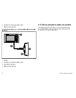
Page 42: ...2 3 4 1 1 Display 2 SeaTalkng to DeviceNet adaptor cable 3 DeviceNetng backbone 4 NMEA 2000 equipment 3 13 Video and alarm audio connection The display supports connection of up to 4 video devices and...

Page 43: ...connection x 4 5 VGA connection to external monitor 6 Audio out line level to appropriate amplifier Video connection colors 1 Black 2 Yellow 3 Green 4 Blue Video and alarm audio cables These are the...

Page 44: ...6 4 ft Video Alarm audio cable A62158 Available as an accessory This cable provides 3 x video input BNC connectors 1 x VGA video output connector 1 x RCA phono jack plug for alarm signalling only Note...

Page 45: ...ter 4 Location and mounting Chapter contents 4 1 Selecting a location on page 46 4 2 Flush mounting on page 48 4 3 Bracket trunnion mounting on page 49 4 4 Front bezel on page 51 Location and mounting...

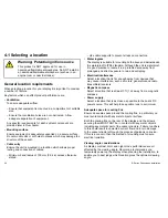
Page 46: ...s waterproof it is good practice to locate it in a protected area away from prolonged and direct exposure to rain and salt spray Electrical interference Select a location that is far enough away from...

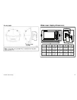
Page 47: ...f equal to or greater than 10 Widescreen display dimensions D11190 2 B E A D C C E90W 316 mm 12 4 A 197 mm 7 8 B 113 mm 4 4 C 156 mm 6 1 D 211 mm 8 3 C E120W 380 mm 15 245 mm 9 6 113 mm 4 4 156 mm 6 1...

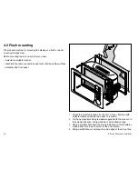
Page 48: ...D11193 2 1 Check the selected location for the unit A clear flat area with suitable clearance behind the panel is required 2 Fix the appropriate cutting template supplied with the product to the sele...

Page 49: ...nd other cables to the unit 9 Slide the unit into place and secure using bolts provided Once you have secured the display in place proceed and attach the front bezel 4 3 Bracket trunnion mounting The...

Page 50: ...lot holes for the screws using a suitable drill taking care that there are no cables or anything that may be damaged behind the surface 3 Use the screws supplied to attach the mounting bracket securel...

Page 51: ...ottom edge of the bezel are latched into position D11196 2 3 Ensure that the control buttons pass through their respective openings 4 Apply firm but even pressure to the bezel along the i Outer edges...

Page 52: ...l doing so may cause damage 1 Unclip the lower edge of the bezel Starting at the lower center edge and working towards the outer edges 2 Unclip the left hand edge working from the bottom corner upward...

Page 53: ...on page 54 5 2 Designating the data master on page 55 5 3 GPS check on page 55 5 4 Radar check on page 56 5 5 Sonar check on page 58 5 6 Language selection on page 59 5 7 Setting up Autopilot AIS and...

Page 54: ...d or moored You may find it helpful to use the simulator mode accessible from Menu System Setup Menu in these situations Note To disable the audible beep that you hear when you touch the screen go to...

Page 55: ...on 5 3 GPS check Checking GPS operation You can check that the GPS is functioning correctly using the chart application 1 Select the Chart page 2 Check the screen With the chart displayed you should s...

Page 56: ...Tx Stdby softkey and set to Tx The scanners should now be transmitting and receiving 4 Check that the radar screen is operating correctly Typical HD digital radar screen Note The example above is repr...

Page 57: ...dar page displayed 1 Select the RADAR SETUP BEARING ALIGNMENT menu 2 Press the BEARING ALIGNMENT softkey 3 Use the rotary control to place the selected target under the Ship s Heading Marker 4 Press O...

Page 58: ...the fishfinder transducer From the main fishfinder screen 1 Press the MENU button 2 Select Fishfinder Setup from the list of options 3 Select Transducer Settings from the list of menu options 4 Use t...

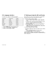
Page 59: ...stem Setup System Integration menu ii Autopilot control This option should be Enabled if you wish to control a compatible autopilot using the display iii NMEA port settings These should be set appropr...

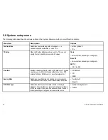
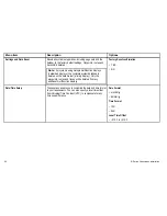
Page 60: ...F 1 2 09 9 to 09 9 Simulator Enables or disables simulator mode which allows you to practice operating your multifunction display without data from a GPS antenna fishfinder DSM sonar or any other exte...

Page 61: ...ensation value that you want to use This value is also transmitted to any other connected SeaTalk instruments 0 degrees East default Range 0 to 30 degrees East or West Language Determines the language...

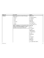
Page 62: ...d on the data master primary display Only the waypoints routes and tracks will be deleted from any additional multifunction displays Factory Reset confirmation YES NO Date Time Setup These options ena...

Page 63: ...than 1 unit the system displays the units in Feet If the Distance unit is set to Kilometers the system displays the units in Meters Distance Units Nautical Miles default Statute Miles Kilometers Spee...

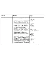
Page 64: ...o OFF the alarms will NOT be displayed on your multifunction display Preferred GPS Source Your multifunction display supports GPS receivers connected by SeaTalk1 SeaTalkng or NMEA2000 Select the prefe...

Page 65: ...enable or disable the individual NMEA output sentences for each NMEA port NMEA Port Setting Allows you to specify the appropriate port speed for the equipment connected to each NMEA port When the Nav...

Page 66: ...Navtex 4800 Navtex 9600 AIS 38400 Waypoint Password Setup This menu allows you to enable password protection for waypoints and to change the password Enable Password OFF default ON Change Password Di...

Page 67: ...oubleshooting on page 70 6 4 GPS troubleshooting on page 71 6 5 Sonar troubleshooting on page 72 6 6 System data troubleshooting on page 73 6 7 Video troubleshooting on page 74 6 8 Touchscreen trouble...

Page 68: ...ected to comprehensive test and quality assurance programs However if you experience problems with the operation of your E Series Widescreen multifunction display this section will help you to diagnos...

Page 69: ...ble causes Possible solutions Check relevant fuses and breakers Check that the power supply cable is sound and that all connections are tight and free from corrosion The display does not start up Prob...

Page 70: ...alkhs switch Check the status of the SeaTalkhs Switch SeaTalkhs network problem Check that SeaTalkhs cables are free from damage Software mismatch between equipment may prevent communication Contact R...

Page 71: ...GPS connection fault Ensure that GPS connections and cabling are correct and fault free External GPS antenna in poor position For example Below decks Close proximity to transmitting equipment such as...

Page 72: ...khs network problem Check that SeaTalkhs cables are free from damage No data source for the fishfinder Software mismatch between equipment may prevent communication Contact Raymarine technical support...

Page 73: ...70 instrument or engine interface Check the power to the SeaTalk bus Data source e g ST70 instrument or engine interface is not operating Refer to the manufacturer s handbook for the equipment in ques...

Page 74: ...No signal message on screen video image not displayed Cable or connection fault Check that the connections are sound and free from corrosion Only 1 video connection available Video inputs 2 3 and 4 a...

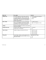
Page 75: ...calibrate the touchscreen Touchscreen does not operate as expected Saltwater deposits on the screen Carefully clean and dry the screen in accordance with the instructions provided 6 9 SeaTalkhs LED i...

Page 76: ...Ensure that the front bezel is fitted correctly and that all buttons are free to operate correctly Software mismatch on system upgrade required Go to www raymarine com and click on support for the lat...

Page 77: ...Chapter 7 Technical support Chapter contents 7 1 Raymarine technical support on page 78 7 2 3rd party support on page 79 Technical support 77...

Page 78: ...he Raymarine Technical Support Department and details of worldwide Raymarine agents Telephone support In the USA call 1 603 881 5200 extension 2444 In the UK Europe the Middle East or Far East call 44...

Page 79: ...Contact and support details for 3rd party suppliers can be found on the appropriate websites Navionics www navionics com Sirius marine weather www sirius com marineweather Sirius audio www sirius com...

Page 80: ...80 E Series Widescreen installation...

Page 81: ...Chapter 8 Technical specification Chapter contents 8 1 Technical specification on page 82 Technical specification 81...

Page 82: ...nce manual for further information 1 Environmental Installation environment Operating temperature 10 C to 50 C 14 F to 122 F Storage temperature 20 C to 65 C 4 F to 149 F Relative humidity max 95 Wate...

Page 83: ...output 1V rms line level into 600R load Video input 4 x NTSC PAL video inputs to ITU R BT 601 standard Video output 1 x VGA output at either 720p 1280 x 720 or native display resolution Electronic ch...

Page 84: ...84 E Series Widescreen installation...

Page 85: ...tions and accessories Chapter contents 9 1 SeaTalk accessories on page 86 9 2 SeaTalkng accessories on page 86 9 3 SeaTalkhs accessories on page 87 9 4 Spares and accessories on page 89 Options and ac...

Page 86: ...extension cable D288 9 2 SeaTalkng accessories SeaTalkng cables and accessories for use with compatible products Description Part No Notes Backbone Kit A25062 Includes 2 x 5 m 16 4 ft Backbone cable...

Page 87: ...er cables Scanner cables Connect the Radar scanner to either the SeaTalkhs switch or the crossover coupler Cable Part number Notes 5 m 16 4 ft Digital cable A55076 10 m 32 8 ft Digital cable A55077 Yo...

Page 88: ...s network cable E55052 Fully waterproof SeaTalkhs network cables Connect directly from display to display Cable Part number Notes 1 5 m 4 9 ft Dual end SeaTalkhs network cable A62245 Cable has waterpr...

Page 89: ...on bracket mount kit C140W E140W A62134 5 m 16 4 ft Audio Video cable A62158 Available as an accessory This cable provides 3 x video input BNC connectors 1 x VGA video output connector 1 x RCA phono j...

Page 90: ...to service dealers only Description Part No Notes Chart door R62184 Seal Set C90W E90W R62186 Description Part No Notes Seal Set C120W E120W R62187 Seal Set C140W E140W R62188 Front panel C90W E90W R6...

Page 91: ...r PCB assembly R62252 I O PCB Assembly R62253 CPU PCB Assembly R62254 Keymat Set R62270 SSD PCB Assembly US version R62255 SSD PCB Assembly EU version R62298 SSD PCB Assembly ROW version R62299 UniCon...

Page 92: ...92 E Series Widescreen installation...

Page 93: ...er of protocols to transfer data between the various devices in your networked system The following table details which devices may be connected to your display and the type of connectivity in terms o...

Page 94: ...0 Third party AIS Class A or Class B receiver transceiver NMEA 0183 SeaTalkng Device Type Suitable Devices Connectivity Navtex Navtex Receiver NMEA 0183 Fast Heading Sensor Fast Heading Sensor NMEA 01...

Page 95: ...position latitude longitude GSA GPS DOP and active satellites GSV GPS satellites in view RMA Recommended minimum specific loran c data RMC Recommended minimum specific GPS transit data VTG Course ove...

Page 96: ...WMV Wind speed and angle sentence RMA Recommended minimum specific loran c data sentence RMB Recommended minimum navigation information sentence RMC Recommended minimum specific GPS transit data sent...

Page 97: ...quest 60928 ISO Address Claim 126208 NMEA Acknowledge group function 126464 PGN List 126992 System time 126996 Product information 127237 Heading Track Control 127245 Rudder 127250 Vessel heading 1274...

Page 98: ...on data 129291 Set and drift rapid update 129301 Time to or from mark 129539 NMEA 2000 GNSS DOPs message 129540 GNSS Sats in view 129545 NMEA 2000 GNSS RAIM output message 129550 GNSS differential cor...

Page 99: ...16 19 10 11 12 9 5 6 Item Remarks Identification PWR NMEA ST Video Connector type 19 pin twist lock Item Remarks Current source to network No current sourced for external devices Current sink from net...

Page 100: ...Blue White NMEA3 RX 2 7 0 15 26 Twisted pair Blue Green ST1 BATT 10 7 0 15 26 White Red ST1 DATA 12 7 0 15 26 White Yellow HONK 16 7 0 15 26 Grey Signal Pin Cable AWG Group ing Color ST1 BATT 14 7 0 1...

Page 101: ...19 VIDEO OUT BLUE 20 VIDEO OUT BLUE GROUND SeaTalkhs connector 1 8 Item Remarks Identification STHS Connector type RJ45 with suitable waterproofing Current source to network No current sourced for ext...

Page 102: ...source to network No current sourced for external devices Current sink from network 160mA Interface drive only Pin Signal 1 12V 2 0V 3 Screen 4 CanH 5 CanL 6 SeaTalk not connected on C E Series Widesc...

Page 103: ......

Page 104: ...www raymarine com...

Reviews: