background image

24

DS400 and DS500 Digital Fishfinders

Operation and Maintenance

Releasing the transducer

The transducer releases easily when it is fastened to the hull. Give a sharp 
blow to the bottom of the transducer using the palm of the hand. 

CAUTION:  

Never strike the transducer with anything except the palm of the hand. 
Never strike the paddlewheel

Antifouling Paint

Marine growth can accumulate rapidly on the transducer’s surface reducing 
performance within weeks. Surfaces exposed to salt water that do not 
interlock, 

must

 be coated with anti-fouling paint. Use 

water-based

 anti-

fouling paint only. 

Never

 use ketone-based paint, since ketones can attack 

many types of plastic possibly causing damage to the transducer. Apply paint 
every 6 months or at the beginning of each boating season.

Cleaning

Clean the transducer with a soft cloth and mild household detergent. If 
fouling occurs, use a stiff brush or putty knife to remove the growth 

being 

careful

 to avoid scratching the transducer’s face. In severe cases, wet sand the 

paddlewheel with fine grade wet/dry paper.

Servicing the Paddlewheel

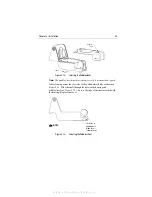
If the paddlewheel becomes fouled or inoperable, remove it for cleaning. 
Remove the cover by depressing the latch near the paddlewheel. Using a 
small finish nail, push the shaft out. (see 

Figure 2-12 

).

bereitgestellt von Busse-Yachtshop.de

Summary of Contents for DS400

Page 1: ...DS400 DS500 Digital Fishfinders Owner s Handbook Document number 81234 1 Date December 2003 bereitgestellt von Busse Yachtshop de...

Page 2: ...bereitgestellt von Busse Yachtshop de...
Page 3: ...ntained in this handbook to the best of our knowledge was correct as it went to press However the Raymarine policy of continuous improvement and updating may change product specifications without prio...

Page 4: ...formance is not compromised Although every effort has been taken to ensure that they will perform under all conditions it is important to understand what factors could affect the operation of the prod...

Page 5: ...ns there are no user serviceable parts or adjustments 3 NAVIGATION AID This unit is only an aid to navigation Its accuracy can be affected by many factors including equipment failure or defects enviro...

Page 6: ...formation on Raymarine products and services contact either of the following United States Raymarine Incorporated 22 Cotton Road Unit D Nashua New Hampshire 03063 4219 USA Telephone 1 603 881 5200 1 8...

Page 7: ...ipment Location 7 Mounting Location 7 2 4 Cable Runs 8 2 5 Mounting the Fishfinder 11 Bracket Mounting 11 Console Mounting optional 11 2 6 System Connections 13 DC Power Connection 13 Transducer Conne...

Page 8: ...ble Range Marker VRM 39 Chapter 4 Menu Operation 41 4 1 Introduction 41 4 2 Fishfinder Operation Controls 42 Scroll Speed 43 Range 43 Hunt Mode 45 Frequency 45 A Scope 46 GAIN MODE 47 GAIN 48 Color Ga...

Page 9: ...gh 69 Temp Rng Low 69 ALARM CLOCK 70 UNITS 71 Depth Units 71 Temp Units 71 Speed Units 71 Distance Units 71 Bearing Mode 71 Date Format 71 Time Format 72 NMEA OUT SET UP 72 Language 73 Key Beep 73 Key...

Page 10: ...to Contact Raymarine 78 On the Internet 78 Customer Support 78 In the US 78 Accessories and Parts 78 Technical Support 79 Product Repair and Service 79 In Europe 80 Technical Support 80 Accessories an...

Page 11: ...artHighDefinitionFishImaging HDFI technology Constantly adjusting transmitter and receiver parameters the DS400 DS500 intelligently analyzes fish and bottom echoes and automatically produces a crysta...

Page 12: ...nsmissive High Brightness TFT Color LCD DS400 3 5 Transflective Daylight Viewable TFT Color LCD VGA 76 800 Pixel Display Resolution Patented Digital HDFI Technology Hands Off Adaptive Auto Adjustments...

Page 13: ...nder models It is important to position your transducer correctly Details on your transducer including location and installation instructions are included in the transducer box Note Instructions for m...

Page 14: ...4 DS400 and DS500 Digital Fishfinders bereitgestellt von Busse Yachtshop de...

Page 15: ...ll your system plan the installation considering Location of the fishfinder as described in Section 2 3 Cable Runs as described in Section 2 4 Suppression Ferrites The following illustration shows typ...

Page 16: ...hfinder without Transducer US version DS500 Digital Fishfinder without Transducer CE version E63061 E63062 E63063 E63064 supplied supplied supplied supplied Sun Cover DS400 Sun Cover DS500 R69070 R690...

Page 17: ...ices that may cause interference such as motors generators and radio transmitter receivers see the EMC guidelines earlier in this sec tion Magnetic compass Mount the unit at least 3 ft 1m away from a...

Page 18: ...as aconnectorplugatoneendforconnectingtothefishfinder and3wiresat the other end for connecting the power supply The power cable may be extended byup to 60ft 20 m using a wire gauge of AWG 12 orgreater...

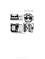
Page 19: ...nit Dimensions 2 28 in 57 9 mm 5 88 in 149 4 mm 5 12 in 130 mm 4 45 in 113 mm 5 0 in 127 mm 3 17 in 80 5 mm 1 3 in 33 2 mm 2 70 in 68 6 mm 2 99 in 76 mm 2 83 in 72 mm 3 46 in 88 mm D6440 1 2 28 in 57...

Page 20: ...DS500 Unit Dimensions 3 46 in 88 mm 5 88 in 149 4 mm 2 66 in 67 6 mm 3 08 in 78 3 mm 2 99 in 76 mm 2 83 72 m 6 37 in 161 8 mm 3 81 in 96 7 mm 5 9 in 150 mm 6 22 in 158 mm D6448 1 2 66 in 67 6 mm 1 68...

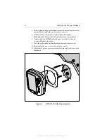
Page 21: ...hten the knobs Console Mounting optional The fishfinder may also be installed directly into the console This requires thepurchaseofanoptionalFlushMountkit RaymarinepartnumberE66067 for DS400 or E66068...

Page 22: ...o the holes provided at the rear of the unit 8 Connect the Power NMEA cable and transducer cables to the unit Avoid tight bends in the cables 9 Place the gasket on the unit and slide the unit into the...

Page 23: ...utput of the battery isolator switch or at a DC power distribution panel Raymarine recommends that power is fed directly to the DS400 500 via its own dedicated cable system A 2 amp fast blow fuse is a...

Page 24: ...tting the cable ensure that any holes you drill are large enough to accept the connector with the nut removed approximately 13 16 or 21 mm Before attaching the transducer cable you will need to attach...

Page 25: ...is powered on can cause sparks Only remove the transducer cable after power has been removed from the DS400 500 If the transducer cable is accidentally removed while the DS400 500 is powered on remov...

Page 26: ...ics greatly reducing their strength Applications Not recommended for boats with large or twin screw inboard engine s Requires 89mm 3 1 2 of headroom to install Good operation up to 44kts 50MPH Vertica...

Page 27: ...of the boat as possible On slower heavier displacement hulls positioning it farther from the centerline is acceptable Do not mount in an area of turbulence or bubbles Near water intake or discharge o...

Page 28: ...uts into the slots in the back of the bracket 3 Aligned the holes in the transducer bracket and nuts Insert the two machine screws capturing the nuts Tighten the machine screws until the transducer wi...

Page 29: ...nsom angle The shim is not needed for this installation Skip to Mounting the Bracket Stepped transom and jet boats 3 transom angle Usethe shimwith the tapered end down Be sure the nuts are in the slot...

Page 30: ...hull seeFigure2 9 Thestern ofthetransducershould be1 3mm 1 16 1 8 belowthebowofthetransducerorparalleltothe bottom of the hull Figure 2 9 Transducer Angle Adjustment 2 Using the vertical adjustment sp...

Page 31: ...not gradual identify the boat speed at which the onset occurred Return the boat to this speed then gradually increase speed while making moderate turns in both directions 4 If the performance improve...

Page 32: ...rine sealant to the threads of the 10 x 1 3 4 self tapping screw to prevent water seepage into the transom Tighten the screw Figure 2 11 Stabilizing the Bracket Cable Routing Routethetransducercableov...

Page 33: ...eping into the transom If you have drilled a hole through the transom apply marine sealant to the space around the cable where it passes through the transom 8 Position the two cable clamps and fasten...

Page 34: ...t Use water based anti fouling paint only Never use ketone based paint since ketones can attack manytypesofplasticpossiblycausingdamagetothetransducer Applypaint every 6 months or at the beginning of...

Page 35: ...the paddlewheel blade as shown in Figure 2 13 Slide the shaft through the holes in the housing and paddlewheel see Figure 2 12 Be sure the ends of the shaft are flush with the housing Replace the cove...

Page 36: ...26 DS400 and DS500 Digital Fishfinders bereitgestellt von Busse Yachtshop de...
Page 37: ...up your DS400 500 and display are given in Chapter 6 3 3 Simulator Mode If you have not fully installed the fishfinder you can still operate in Simulator mode by connecting the fishfinder to a 12VDC p...

Page 38: ...structures such as a reef or shipwreck The upper and lower depth range limits are shown You can customize the sounder by choosing what is displayed and how it is displayed including language and units...

Page 39: ...Figure 3 2 Typical Fishfinder Display Screen 40 20 60 60 43 44 44 43 43 47 47 42 ft 35 36 Water surface Depth markers Target image fish arch Range Bottom depth Frequency Image depth D6637 1 bereitges...

Page 40: ...own on the display TRACKPAD WhenaMenuitemhasmorethanonepossibleresponse usetheleftandright arrow keys to change the value When a menu item appears in UPPER CASE it contains sub menus Press the right a...

Page 41: ...aph display PWR Press to turn on the fishfinder Press and hold for three seconds to turn unit off Press and release as a shortcut to the DISPLAY SET UP menu 3 6 Selecting the Display Page The DS400 an...

Page 42: ...74 68 69 70 71 72 73 74 Minutes Temperature 71 5 F Speed kts 4 6 Log Trip 50 2 V 13 5 ft nm nm Position Waypoint m nm AM F V h SOG COG TTG Time Battery 13 7 Temperature 71 7 Date WPT BRG WPT RNG N 26...

Page 43: ...ions Figure 3 5 Accessing the Main Menu Figure 3 5 identifies these groupings General Menu Controls are described in Chapter 4 Display Setup functions are described in Chapter 5 Sounder Setup function...

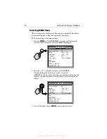
Page 44: ...ing the key down to scroll at a faster rate GAIN MODE contains sub menu items you can change All menu items that have sub menus are shown with all capital letters followed by an ellipsis 3 Press the t...

Page 45: ...trackpad to browse to MANUAL ii Press ENTER to accept The MANUAL field is no longer highlighted iii Use the trackpad to increment decrement the value iv Press ENTER again to accept The MANUAL field is...

Page 46: ...1 ENTER ENTER GAIN MODE GAIN MODE COLOR GAIN Second Echo Rej AUTOMATIC GAIN MANUAL 50 TVG AUTOMATIC Max Ping Rate Power Sounder Int Rej AUTO FISHING LOW AUTOMATIC 30 GAIN MODE GAIN MODE COLOR GAIN Sec...

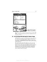
Page 47: ...different colors You can use this information to determine the size of fish and the bottom structure Other objects in the water such as debris and air bubbles also return echoes these echoes are gener...

Page 48: ...size of fish arches on the image A fish with a large swim bladder produces a large fish arch while a fish with a small one produces a small arch Several arches together show a school of fish Figure 3...

Page 49: ...the main fishfinder page TheVRM isdisplayedasaverticallinerunningtheentire heightofthedisplay Youcan usethe and keysofthetrackpadtomovetheVRMoveraparticularobject to reference it from the boat Distanc...

Page 50: ...40 DS400 and DS500 Digital Fishfinders Figure 3 7 Using VRM 40 20 60 60 ft 75ft 75ft 75ft VRM D6640 1 Distance from boat bereitgestellt von Busse Yachtshop de...

Page 51: ...item 3 Press the trackpad or keys to select the desired option For menu items with sub menu items menu title in all CAPITALS press the trackpad key or ENTER to browse the sub menus 4 Press QUIT to ex...

Page 52: ...MATIC 200 kHz MAN 50 kHz MAN DUAL MAN AUTOMATIC A Scope OFF ON 1 ON 2 ON 3 OFF GAIN MODE GAIN AUTO FISHING AUTO TROLLING AUTO CRUISING MANUAL 0 99 AUTO FISHING COLOR GAIN AUTOMATIC MANUAL 0 99 AUTOMAT...

Page 53: ...syouto selectthe maximum depth displayed on the scrolling bottom and A Scope displays This parameter determines whether the depth range displayed is set automatically by the sounder or manually using...

Page 54: ...n makethe changeifdesired If you wishto remain in Automatic Range mode press QUIT The following range shift values are available Table 4 2 Range Values Feet Fathoms Meters CE models only 5 1 2 10 2 4...

Page 55: ...ge auto frequency and bottomiscurrentlydetectedat250ftusing200kHz Thebottomsignalbecomes lost so the sounder switches to Hunt mode Pinging begins at 250 ft the last known good depth using 200 kHz and...

Page 56: ...me If you choose dual frequency operation the scrolling bottom dis play is split vertically the left half shows the 200 kHz detailed view and the right half shows the 50 kHz image The default setting...

Page 57: ...n settings take advantage of the hardware s advanced digital technology As a result the sounder typically performs better in auto matic mode thanmanual For betterperformanceRaymarine recommends select...

Page 58: ...level for you based on depth and water conditions Automatic gain modes take advantage of the hardware s advanced HDFI technology As a result the sounder typically achieves a sharper image in any of th...

Page 59: ...asmall signal bandforthe othercolors setting a high value givesa widebandforthe strongest colors but a small signal band for the other col ors If youselect manual adjustment youwill need to re adjust...

Page 60: ...h offers the greatest signal rejection by decreasing the ping rate further The default setting is LOW Only setthissettingto HIGHifyounoticesecond echoes appear on your display Power The Power setting...

Page 61: ...s the display is not zoomed SPLIT means the display is split vertically with the zoom image in the left hand window and the scrolling bottom display in the right hand window See Figure 4 3 In a split...

Page 62: ...hezoom the smaller the area you are viewing so the smaller the Zoom Range Bar Select from x2 x3 x4 Mode AUTOMATIC adjusts the position of the zoom window so that bottom details are always in view MANU...

Page 63: ...have the option to press QUIT to exit without resetting ENTER to confirm the reset DISPLAY SET UP These settings determine how information is displayed on the screen Options are described in Chapter 5...

Page 64: ...54 DS400 and DS500 Digital Fishfinders bereitgestellt von Busse Yachtshop de...

Page 65: ...Set Up menu items 1 Press the MENU key The Main Menu appears 2 Press the trackpad keys to navigate to DISPLAY SET UP 3 Press the trackpad key or ENTER to select 4 Press the trackpad keys to browse to...

Page 66: ...HING DISPLAY SET UP SOUNDER SET UP TRIP RESET MAIN MENU MAIN MENU Range Frequency AUTOMATIC AUTOMATIC Scroll Speed ON A Scope OFF GAIN MODE ZOOM AUTO FISHING DISPLAY SET UP SOUNDER SET UP TRIP RESET M...

Page 67: ...th ID OFF DEPTH FISH FISH DEPTH OFF Depth Digit Size LARGE SMALL LARGE Transparent Menu OFF ON OFF PALETTE Selection CLASSIC SUNBURST GRAYSCALE INV GRAY COPPER NIGHT VISION CLASSIC Background Color WH...

Page 68: ...either the depth or a fish icon This is the default setting DEPTH displays the depth just above each fish echo FISH displays a fish icon instead of an echo Three different fish icons appear representi...

Page 69: ...lor palette The brightness of the screen can be adjusted over a wide range suitable for viewing in daylight high brightness level or at night low brightness level Selection Select the optimal color sc...

Page 70: ...heel Temperature Reading from transducer s thermistor Battery The boat s battery voltage Log Total distance travelled by the boat Trip Distance travelled since the counter was reset Auto Scroll Scroll...

Page 71: ...point Display ON or OFF COG Course Over Ground Display ON or OFF TTG Time to Go before reaching waypoint at current course and speed Display ON or OFF Bearing Mode The mode of all the bearing and head...

Page 72: ...nders Note WhenanaloggaugesareselectedasDataItems theNavigationItems cannot be displayed on the Fishfinder page you need to switch to the Nav Data page using the PAGE key to view this information bere...

Page 73: ...u may decide to customize some aspects At the end are displayed the serial number of your sounder and the software version running This information may be requested by Raymarine staff should technical...

Page 74: ...MENU MAIN MENU Range Frequency AUTOMATIC AUTOMATIC Scroll Speed ON A Scope OFF GAIN MODE ZOOM AUTO FISHING DISPLAY SET UP SOUNDER SET UP TRIP RESET MAIN MENU MAIN MENU SOUNDER SET UP SOUNDER SET UP D6...

Page 75: ...EPTH OFF Fish Alarm ON OFF OFF Shallow Alarm ON OFF OFF Shallow Range 2 1999 FEET 0 332 FATHOMS 1 608 METERS1 5 FEET 1 FATHOM 2 METERS1 Deep Alarm ON OFF OFF Deep Range 3 2000 FEET 1 333 FATHOMS 1 609...

Page 76: ...MAGNETIC TRUE Date Format MM DD YY DD MM YY MM DD YY Time Format 12 HOUR 24 HOUR 12 HOUR NMEA OUT SET BWC BWR DBT DPT GLL MTW VHW VLW VTG ZDA OFF ON OFF Language ENGLISH UK ENGLISH US DANISH FRENCH G...

Page 77: ...visual indicator continues as long as the condition exists Figure 6 2 Alarm Condition You may want to use the shallow and deep water alarms when you are anchored Set the limits to just above and below...

Page 78: ...setting is OFF Shallow Alarm IfthisalarmisON and thedepthbelowtheboatislessthanthevaluesetusing the Shallow Range setting the beeper sounds and moving arrow indicators point to the digital depth disp...

Page 79: ...s if the temperature moves outside the set range If data items are displayed as analog gauges when the alarm is active the temperature value flashes You cannot set the Temp Rng High setting to be lowe...

Page 80: ...NTER The word ON and the time are no longer highlighted 4 Press the or trackpad key to decrement increment the alarm time 5 When the time at which you want the alarm to sound is displayed press ENTERa...

Page 81: ...E Speed Units KNOTS default MILES PER HOUR KM PER HOUR Distance Units NAUTICAL MILES default STATUTE MILES KILO METERS Note VRM distance is measured by the transducer s paddlewheel and is based on the...

Page 82: ...ce by selecting OFF The following table displays the available NMEA sentences and their meanings 1 Data repeated from external device Table 6 2 NMEA Sentences Sentence Meaning BWC Bearing Distance to...

Page 83: ...When Help is set to ON icons appear next to the digital depth display prompting you to make the appropriate key presses The help message is cleared when an action is selected See page 37 for an illust...

Page 84: ...temperature calibrate option enables you to adjustthedisplayedtemperature in0 1degreeincrementsofthetemperature units you have assigned using the UNITS parameter See page 71 Sounder Simulator The sim...

Page 85: ...tenance procedures are therefore limited to the following periodic checks Examine the cables for signs of damage such as chafing cuts or nicks Check that the cable connectors are firmly attached Clean...

Page 86: ...es and replacementpartsusedwillnotaffectperformance Therearenouserser viceable parts in any Raymarine product Some products generate high voltages so never handle the cables con nectors when power is...

Page 87: ...se Display freezes 1 Check the Scroll Speed is not set to PAUSE 2 Check the transducer cable for damage If damaged the cable and transducer must be replaced as a unit Unit does not display fish 1 Fish...

Page 88: ...nd Answers link routes you to our solution database Search questions and answers by product category keywords or phrases If the answer you are seeking is not available click the Ask Raymarine tab to s...

Page 89: ...e available to answer questions about installing operating and trouble shooting all Raymarine products Questions can be sent directly to our Technical Support Department via the Internet Point your br...

Page 90: ...zed dealer or contact Raymarine Ltd Anchorage Park Portsmouth Hampshire England PO3 5TD Tel 44 0 23 9269 3611 Fax 44 0 23 9269 4642 Technical Support The Technical Services Department handles inquirie...

Page 91: ...0 C Humidity up to 95 at 35 C non condensing Power Input 10 0VDC to 18 0VDC 13 8 VDC nominal Consumption Typical 10W 12VDC Mounting Mounting Bracket or optional Flush Mount Controls 5 defined keys and...

Page 92: ...82 DS400 and DS500 Fishfinders NMEA Data Connector Received Transmitted POWER NMEA BWC BWR GLL ZDA RMB VTG HDG HDT BWC BWR DBT DPT GLL MTW VHW VLW VTG ZDA bereitgestellt von Busse Yachtshop de...

Page 93: ...0 Analog Gauges 60 Auto Scroll 60 Battery 60 Log 60 Speed 60 Temperature 60 Trip 60 Date Format 61 71 Date Setting 61 Deep Alarm 68 Deep Range 69 Depth Digit Size 59 Depth Offset 73 Depth Units 71 Dim...

Page 94: ...73 Key Help 73 Keypad 30 L Language 73 LAT LONG 61 List Display Set Up Menu items 57 Main Menu items 42 Sounder Set Up Menu items 65 Location Mounting 7 Log 60 M Main Menu 33 41 List 42 Maintenance 75...

Page 95: ...Number 74 Service 79 Shallow Alarm 68 Shallow Range 68 Simulator 27 74 Software Version 74 SOG 61 Sonar Echoes 28 Fish Indications 38 Image 37 Signal Strength 37 Sounder Basic System 3 Sounder Setup...

Page 96: ...e Format 61 72 Time Offset 61 Time Setting 61 Trackpad 30 Transducer 3 Cable 14 Cleaning 75 Connections 13 14 Frequency 38 Installing 16 Transparent Menu 59 Trip 60 Trip Reset 53 TTG 61 TVG 49 U Units...

Reviews: