Raymarine Digital Radome RD418D User Manual Download Page 5

 Important information

                             1

Important information

Introduction

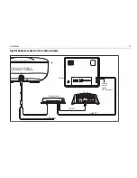
This handbook contains an explanation of how to install, connect and
maintain your Digital Radome scanner and covers the following models:
• RD418D - 18” 4 kW Digital Radome scanner.
• RD424D - 24” 4 kW Digital Radome scanner.
Your radar has been designed and manufactured to meet the rigorous
demands of the marine environment. However, no machine can perform its
intended function unless installed, operated and maintained properly.
Please carefully read and follow the recommended procedures for installa-
tion contained in this handbook.
When properly installed and operated, the use of this radar  conforms to:
• IEEE C95.1 - 2005 - Standard for Safety Levels with respect to Human

Exposure to Radio Frequency Electromagnetic Fields, 3 kHz to 300GHz.

• ICNIRP Guidelines 1998 - International Commission on Non-Ionising

Radiation Protection: Guidelines for limiting exposure to time-varying
electric, magnetic and electro-magnetic fields (up to 300GHz) 1998.

Intended use

This product is a radar scanner intended for use within a navigational radar
system. The intended application is for leisure marine boats and work
boats not covered by IMO/SOLAS carriage requirements.
Installation and operation of this radar may be subject to individual 
licensing of the equipment, operator or vessel.  You are strongly advised to 
check with the requirements of the licensing authority of your national 
administration.  In case of difficulty, contact your local Raymarine dealer.

Safety notices


WARNING

Radio Frequency Radiation Hazard

The radar antenna emits electromagnetic energy at micro-
wave radio frequencies which can be harmful, particularly to 
your eyes.  DO NOT look at the antenna at close range.
It is important that the radar is turned off whenever personnel 
are required to come close to the scanner assembly. It is 
recommended that the radar scanner is mounted out of range 
of personnel (above head height).
The maximum power density level which is considered safe for 
general public exposure is 10 W/m

2

, and for occupational expo-

sure it is 100 W/m

2

. The distances from the radar scanner 

within which these levels may be exceeded are given below:

Model

Distance to 100 W/m

2


point

Distance to 10 W/m

2


point

RD418D

Max power density at any 

distance is <100 W/m

2

 1.0m (worst case)

RD424D

Max power density at any 

distance is <100 W/m

2

1.0m (worst case)

Summary of Contents for Digital Radome RD418D

Page 1: ...87092 1 Raymarine A5 Landscape Special Cover_Front eps Digital Radome Scanner User Guide Document number 81313 3 Date February 2009...

Page 2: ...oldings Limited 45STV 60STV AST Autoadapt Auto GST AutoSeastate AutoTrim Bidata GSeries HDFI LifeTag Marine Intelligence Maxiview On Board Raychart Raynav Raypilot RayTalk Raystar ST40 ST60 Seaclutter...

Page 3: ...red tools 6 Digital Radome scanner dimensions 7 18 Digital Radome scanner 7 24 Digital Radome scanner 7 Planning the installation 8 Cable requirements 9 Scanner cables 9 Running the cable to the scann...

Page 4: ...ii Digital Radome Scanner User Guide...

Page 5: ...em The intended application is for leisure marine boats and work boats not covered by IMO SOLAS carriage requirements Installation and operation of this radar may be subject to individual licensing of...

Page 6: ...est industry standards for use in the recreational marine environment The design and manufacture of Raymarine equipment and accessories conform to the appropriate Electromagnetic Compatibility EMC sta...

Page 7: ...the navigation warning screen However if a scanner is not connected to the multi function display the version number will only be displayed for 10 seconds For information on how to update your multi...

Page 8: ...4 Digital Radome Scanner User Guide...

Page 9: ...ormance within the constraints imposed by any location always ensure the maximum separation possible between different items of electrical equipment For optimum EMC performance it is recommended where...

Page 10: ...Denso Paste Handbook Required tools Radome Scanner Installation template D11364 2 Drill 4 holes 10 mm diameter 18 and 24 Radomes 141 5 mm 27 5 mm 18 or 24 Radome Mounting Template Center Line of Radom...

Page 11: ...dome scanner 346 mm 13 62 in diameter 521 mm 20 5 in diameter 233 mm 9 17 in D11356 1 247 mm 9 7 in 116 5 mm 4 58 in 141 5 mm 5 57 in 27 5 mm 0 92 in D11357 1 247 mm 9 7 in 233 mm 9 17 in 116 5 mm 4 5...

Page 12: ...t the scanner so high that it is affected by the pitching and rolling of the boat Mount the scanner so that the array rotates parallel to the waterline The radar beam is approximately 25o wide in the...

Page 13: ...st and connected to the unit Make sure that the cable does not chafe where it enters and exits the mast To minimize electrical interference try to avoid running radar cables near other onboard electri...

Page 14: ...must be protected by a thermal circuit breaker or fuse fitted close to the power source The following table details the fuse requirements for both 18 and 24 Digital Radomes WARNING If there is not a...

Page 15: ...Care should be taken to ensure a firm connection between the Digital Radome s external connector and the digital cable connector The digital cable connection to the Digital Radome scanner must be han...

Page 16: ...12 Digital Radome Scanner User Guide Digital Radome connected to networked E Series Radar D11391 1 12 24V power SeaTalkhs SeaTalkhs SeaTalkhs Switch...

Page 17: ...Installation 13 Digital Radome connected to G Series display D11373 1 12 24V power SeaTalkhs Network selector switch in UP position Monitor GPM 400 SeaTalkhs Radar SeaTalkhs Switch...

Page 18: ...sure mounting platform is adequately robust for this installation F O R W A R D 1 1 Tape template to mounting platform 2 Using template drill 10 mm diameter hole in 4 positions D ri ll 4 h o le s 1 0...

Page 19: ...bolt in to the base of the scanner as shown in the following diagram Setting up the scanner Before you go to sea It is important to check the installation before you go to sea This involves aligning t...

Page 20: ...n the Digital Radome scanner using the relevant softkey on your multi function display 3 If necessary adjust the brightness on your multi function display unit 4 If necessary change the default langua...

Page 21: ...attach the mounting bolts securing the scanner Troubleshooting The following table will help you identify the most likely cause of a problem and the corrective action required to restore normal opera...

Page 22: ...act your local dealer national distributor or Raymarine technical support for further advice Always quote the product serial number The multi function display unit serial number can be found on the ba...

Page 23: ...at www raymarine com This contains Frequently Asked Questions servicing information e mail access to the Raymarine Technical Support Department and details of worldwide Raymarine agents Telephone supp...

Page 24: ...20 Digital Radome Scanner User Guide...

Page 25: ...range 10 to 55 C Humidity limit upto95 at35 C Maximum wind speed for satisfactory operation 100 Kts Maximum Range Scale 48 Nautical miles Nm Transmitter Transmitter Fre quency 9405 25 MHz Peak Power...

Page 26: ...ominal 4 9 horizontal 25 vertical Polarization Horizontal Rotation Rate 24 rpm nominal Receiver IF Frequency 60 MHz nominal Receiver Characteristic Logarithmic Receiver Noise Figure Less than 5 dB inc...

Page 27: ...Humidity limit upto95 at35 C Maximum wind speed for satisfactory operation 100 Kts Maximum Range Scale 48 Nautical miles Nm Transmitter Transmitter Fre quency 9405 25 MHz Peak Power Output 4 0 kW nom...

Page 28: ...ominal 3 9 horizontal 25 vertical Polarization Horizontal Rotation Rate 24 rpm nominal Receiver IF Frequency 60 MHz nominal Receiver Characteristic Logarithmic Receiver Noise Figure Less than 5 dB inc...

Page 29: ...www raymarine com 0168...

Reviews: