background image

2-10

RayChart 420/420D Chartplotter

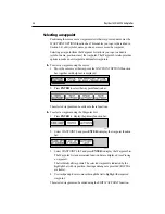
Removing a Nav-Chart card

CAUTION:
DO NOT use a metallic instrument, eg. a screwdriver or pliers, to aid
removal as doing so can cause irreparable damage.

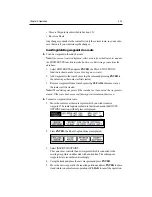
ä To remove a Nav-Chart card:

1. Pull out the cartridge cover at the right hand side of the unit.

2. Grip the card firmly and pull to remove it from its slot.

3. To prevent the ingress of water , replace the cartridge cover.

Note: If difficulty is experienced in removing the card, a short length of cord
can be secured between the two circular holes in the card to ease its removal,
making sure that fitting of the cartridge cover is not impeded
.

Displaying the chart data

The new chart data will be displayed when you move the cursor into an area
covered by the new chart or, if it is already in the area, change the range scale.

The boundary of each chart digitized in the current card is defined by a box or
rectangle. (You can switch off the chart boundaries display if you wish, as part
of the chartplotter set up described in Chapter 4).

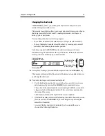
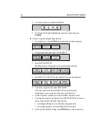
ä To zoom in:

1. Use the trackpad to move the cursor inside one of the chart boxes.

2. Press the lower part of the RANGE key.

That area is expanded to show more detail. The smaller the chart box is on
the screen, the greater the detail that is available when you zoom in.

Unless you have activated Plotter Mode (see Chapter 4, Chart Set Up), you
cannot zoom in further than the most detailed chart and you cannot zoom
out further than the world map.

Displaying chart information

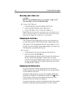
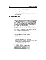
Nav-Chart cards include a number of displayed objects for which data is
available, eg. lights, buoys or ports. Placing the cursor over an object displays
its associated data in a pop-up box.

At large chart scales, placing the cursor over a port symbol enables detailed
information to be displayed. Port information is indicated by the  

 symbol .

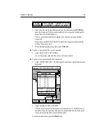
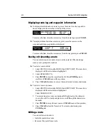
The port facilities are listed in the object information pop-up and, where
available, details for each facility can be displayed.

In some areas the chart shows symbols for individual facilities. These facilities
and symbols are dependent upon  the particular area Nav-Chart card used.

Summary of Contents for Chartplotter

Page 1: ...Distributed by Any reference to Raytheon or RTN in this manual should be interpreted as Raymarine The names Raytheon and RTN are owned by the Raytheon Company...

Page 2: ...Raychart 420 420D Chartplotter Owner s Handbook Documentnumber 81162_2 Date January2000...

Page 3: ......

Page 4: ...justments The operator should never remove the display unit cover or attempt to service the equipment 2 NAVIGATIONAID This device is only an aid to navigation Its accuracy can be affected by many fact...

Page 5: ...irePO35TD England Telephone 44 0 23 9269 3611 Fax 44 0 23 9269 4642 Website www raymarine com Copyright RaytheonMarineCompany1999 The technical and graphical information contained in this handbook to...

Page 6: ...ister your RayChart 420 420D Chartplotter ownership please take a few minutes to fill out the warranty registration card found at the end of this handbook Itisveryimportantthatyoucompletetheownerinfor...

Page 7: ...iv RayChart 420 420D Chartplotter...

Page 8: ...nction bar 1 5 Pop upmenus 1 6 Database lists 1 6 Chapter2 Gettingstarted 2 1 2 1 Introduction 2 1 Conventionsused 2 1 Simulator 2 1 2 2 Switching on off 2 2 Changingthelightingandcontrast 2 2 2 3 Cha...

Page 9: ...nformation 3 12 Erasing or re naming a route 3 12 Inserting deleting waypoints in a route 3 13 3 4 Following routes and going to target points 3 14 Follow a route 3 15 Reversearoute 3 15 Target point...

Page 10: ...4 3 Variation 4 3 Dateformat 4 3 Time offset 4 4 Language 4 4 Simulator 4 4 SimulatedSOG 4 4 SimulatedCOG 4 4 4 3 Chart set up parameters 4 5 Orientation 4 7 Plottermode 4 7 Showwaypoints 4 7 Waypoint...

Page 11: ...5 5 Panelmounting 5 5 5 6 Cabling 5 7 Introduction 5 7 Chartplotter connectors 5 7 GPSconnector 5 7 POWER NMEAconnector 5 8 5 7 SystemCheckandInitialSwitchOn 5 9 EMCConformance 5 9 SystemCheck 5 10 In...

Page 12: ...ts ix How to contact Raytheon Marine Europe 6 5 For accessories and parts 6 5 For technical support 6 5 AppendixA Specification A 1 Appendix B NMEA data B 1 AppendixC Listofabbreviations C 1 Installat...

Page 13: ...x RayChart 420 420D...

Page 14: ...wing routes showingtracksandmanoverboard Chapter 4 Setting Up the Chartplotterprovides instructions for setting up your chartplotter system to suit your preferences It includes instructions for settin...

Page 15: ...and Waypoint Lists Display vessel s track on screen Convert a track to a route SmartRoute SetUpAlarmsandTimers Man OverBoard MOB to navigate back to a missing person or object Satellite acquisition da...

Page 16: ...s are selected in System Set Up and Chart Set Up as described in Chapter 4 1 3 Operating controls The chartplotter is operated by means of the following controls A trackpad providing up down left righ...

Page 17: ...unctions To move the cursor around the chart screen To select an item from a pop up menu or database list To adjust a control setting To enter names in database lists Press the corresponding edge of t...

Page 18: ...ngleaudiobeepconfirmsthekeyaction Ifthekey press is not valid for the current screen or mode three rapid beeps sound to indicate that no response is available If required you can turn the key beeps of...

Page 19: ...e radius of the waypoint arrival alarm and you can set selected navigation data on off Database lists The waypoints and routes that you create on the chartplotter are stored in database lists You can...

Page 20: ...s orasequenceof numberedsteps areindicatedbya symbolinthemargin When textual data is displayed on screen any unavailable data is shown as dashes one per character Where procedures refer to Select this...

Page 21: ...nue Whenyouhavereadandunderstoodthewarning pressthe ENTER key The chart is displayed If this is the first time that the chartplotter has been switched on and no chart cardisinstalled thedisplayshowsth...

Page 22: ...n lighting level is retained until you reset it The new contrast level is retained until you reset it even after power off unless you set the control very low or very high in this case the contrast wi...

Page 23: ...6 PressCLEAR twice to return to the chart screen 2 4 Controlling the display This section describes how to Changethedisplaymode Move around the chart by panning the display changing the chart centre a...

Page 24: ...RNG 12 4 nm ROUTE ROUTE 01 WPT 001 TO WPT 002 WAYPOINT STEER STARBOARD PAGE PAGE PAGE PAGE PAGE PAGE PAGE From Chart Display Press PAGE to display Set Up functions Press to display CDI Press to displ...

Page 25: ...rethevesselusingtheFINDSHIPfunction Changethechartscaleusingthe RANGE keytozoomoutandintoanew area This method is useful if the area you wish to see is some distance away Using FIND SHIP FINDSHIPisuse...

Page 26: ...creases the chart range Decreases the chart range Vertical distance displayed on chart Status Bar For rapid scale change press and hold the required arrow on theRANGE key The distance indicator at the...

Page 27: ...hen you return to a chart scale for which the information is available To zoom out to a smaller scale less detailed chart press the top of the RANGEkeyasmanytimesasrequired 2 5 Using Navionics Nav Cha...

Page 28: ...s of water and consequent damage to the unit always ensure that the cartridge cover is fully and properly inserted whether or not a Nav Chart card is inserted To insert a Nav Chart card 1 Check that y...

Page 29: ...you wish as part of the chartplotter set up described in Chapter 4 Tozoomin 1 Use the trackpad to move the cursor inside one of the chart boxes 2 PressthelowerpartoftheRANGEkey That area is expanded...

Page 30: ...ENTER The details available are listed on screen in an object information pop up D4708_1 INFORMATION FUEL GENERAL SERVICES FIRST AID OTHER UTILITIES WATER REPAIR 3 Use the trackpad to select the requ...

Page 31: ...2 12 RayChart 420 420D Chartplotter...

Page 32: ...ted via NMEA the autopilot will normally prompt for confirmation before it steers the vessel towards the waypoint Ifyouhaveenteredyourrouteusingasmall scalechart zoomintoalarger scale to check for haz...

Page 33: ...the next available number You can use the edit functions to change the symbolandname Whenthecursorispositionedoverawaypoint thewaypoint bearing and range are displayed You can also transfer waypoints...

Page 34: ...scribedin Editing Waypointsbelow 3 Whenfinishedplacingwaypoints press CLEAR To place a waypoint at the vessel s position 1 Select PLACE WPT AT VESSEL A new waypoint is placed at the vessel s current p...

Page 35: ...r together with help text is displayed 2 PressENTER to select the waypoint function bar The selected waypoint can be edited via these functions To select a waypoint using the Waypoint List 1 PressENTE...

Page 36: ...e displayed in the lower half of the window Date and time are included for all waypoints To remove the Waypoint List and return to chart mode pressCLEAR twice Editing the waypoint details Youcanchange...

Page 37: ...DIT WAYPOINT the waypoint edit functions are displayed 5 To edit the waypoint name select EDIT NAME The cursor is placed in the name field of the selected waypoint Edit the name as previously describe...

Page 38: ...own to move through the list to highlight the required waypoint 2 SelectERASEWAYPOINT Press ENTERtoerasethewaypoint To return to chart mode press CLEAR three times Moving a waypoint Youcanmoveanywaypo...

Page 39: ...nd waypoint database to a PC or another navigator When you have created a route you can use the GOTOkey to follow the route TheGOTOkey provides various other options as described in Section 3 4 Up to...

Page 40: ...tomakethe route and select a suitable chart scale 2 Select ROUTES then MAKE ROUTE The MAKE ROUTE function is replaced with PLACE WAYPOINT together with help text 3 Move the cursor to the position on t...

Page 41: ...ave up to 20 named routes in the route database list These routes can then be re displayed and followed subsequently Note When you attempt an operation affecting this route eg CLEAR ROUTE before the c...

Page 42: ...r press CLEAR to cancel the operation 3 Iftheroutehasnotbeensaved apromptgivestheoptionsENTER tosave orCLEAR toremovetheroutefromthescreen 4 To save the route in the database press ENTER TheNameRoute...

Page 43: ...followed by MORE then ROUTE LIST The route list is displayed with the selected route highlighted 2 SelectERASEROUTE 3 PressENTER toerasetheroutefromthelist PressENTER againto confirm orCLEARto cancel...

Page 44: ...outebypressingCLEARinthesamewayas the route was first created Note When deleting waypoints if the route has not been saved the waypoint is erased If the route has been saved the waypoint remains on th...

Page 45: ...ck error this information can be displayed or passed to an autopilot via NMEA You can also restart the Cross Track Error XTE from the actual vessel position to set XTE to zero at that point When the c...

Page 46: ...ely place the cursor over a route leg until the Route functions are displayed 2 Select FOLLOW ROUTE Your vessel s current position becomes the origin and the first waypoint in the current route become...

Page 47: ...h to the target ie it crosses a line passing through the waypoint and perpendicular to the track To cancel the Arrival alarm and go towards the next waypoint in the route pressanykey The target become...

Page 48: ...xt waypoint becomes the target The display is updated to show the new route leg Restart Cross Track Error XTE Reset XTE is useful if you find yourself off track and want to go straight to your target...

Page 49: ...T the waypoint list appears Use the cursor to select the required waypoint D4690_1 TOPSHAM EXETER TEIGNMOUTH EXMOUTH TORQUAY DARTMOUTH PLYMOUTH ENPORT SALCOMBE PORTLAND HARBOUR ISLE O CAP DE LA HAGUE...

Page 50: ...e temporary waypoint is erased Go to a port You can navigate directly to the nearest port or to a selected port or facility To navigate directly to selected port 1 Press theGOTO key and select GOTO PO...

Page 51: ...he target waypoint disappears 3 5 Changing the display mode Use the PAGEkey to select the required display mode Repeat presses of the PAGE keyprovidethefollowingdisplaymodes Set Up functions see Chapt...

Page 52: ...remainsatthetopofthe screen Asthewaypointrangefallsbelow4nm thesymbolmovesdownthe centre line Thechequeredpatternmovesdownthescreentosimulatemovementwhen SOG is greater than2knots The steering instruc...

Page 53: ...tically scales for distance The ranges shown are 4nm 20nm 40nm 100nm 200nm 400nm 1000nm 2000nm 4000nm Ineachcase the range scale has graduations at and of the current scale The steering instruction is...

Page 54: ...a route is being followed and the waypoint is not named the text shows the waypoint number within the route as displayed on screen If a GOTO Cursor or Port is in progress the text indicates GOTOCURSOR...

Page 55: ...comprises text data occupying the whole screen D4703_1 50 45 000 N 001 06 000 W c COG 230 T SOG 6 8 Kts WAYPOINT 001 POSITION STEER STARBOARD BRG 234 T GPS FIX RNG 2 4 nm TIME 14 32 12 12 99 Textual...

Page 56: ...d date in the current format When the Time Date screen is first opened the data relates to the current day unless there is no date information available In this case the last date is used The vessel s...

Page 57: ...points in an unsaved route The RECEIVE WAYPOINTSfunctionaddswaypointsand routesreceivedvia NMEA to the Waypoint List and Route List Note Where multiple waypoints have the same position the last waypoi...

Page 58: ...t a visible fixed wake While the track is turned on it is recorded in the display unit s memory You specify the interval at which track points are made and a line is drawn on screen between each point...

Page 59: ...the current track is retained even when the unit is powered off Setting a short time interval between track points is best suited to navigation withinacloseorcomplexenvironment eg anestuaryormarinawhe...

Page 60: ...K ON SmartRoute SmartRoute enables the latest track to be converted to a route To convert a track into a route 1 SelectMAKEINTOROUTEandpressENTER The current track is converted to a new route with the...

Page 61: ...9 3 9 3 9 3 9 Alarms Alarms Alarms Alarms Alarms The chartplotter reports the following alarms Alarm Indicates Arrival Your vessel has arrived at the active waypoint it has either reached the arrival...

Page 62: ...and default settings The set up parameters are divided into three sections System controlling overall functionality Chart controlling the chartplotting functions including waypoint information and ve...

Page 63: ...their original factory settings if required by performing a factory reset as described in Chapter 6 The following table lists the System menus and their options shows the factory default settings and...

Page 64: ...active Units You can set the units for distance speed and depth The units you set will be used to display all data However the distance units do not affect the chart scale which is always in nautical...

Page 65: ...lly connected equipment The position is initially the position of the cursor when the simulator is switched on and the SOG and COG are as selected by the user The position is updated to reflect the SO...

Page 66: ...rs 1 Press thePAGE key to display the SET UP functions 2 Use the trackpad left right to highlight the CHART SET UP function and pressENTER todisplaytheChartSetUpmenu 3 Use trackpad up down to highligh...

Page 67: ...ew New New New New Default Default Default Default Default Setting Setting Setting Setting Setting ORIENTATION NORTHUP NORTHUP COURSEUP HEADUP PLOTTERMODE OFF ON ON SHOWWAYPOINTS OFF ON ON WAYPOINTSYM...

Page 68: ...to maintain orientation Note Head Up and Course Up modes are dependent upon a valid GPS fix Plotter mode Plotter mode allows the user to zoom in beyond the level of cartography and continue to use pl...

Page 69: ...oaching the target waypoint this is the distance at which the arrival alarm sounds The selected setting is retained when unit switched off Arrival criteria are met when the arrival circle is entered o...

Page 70: ...e unit switched off The default calibration offset is zero To perform position calibration 1 Usinghorizontaltrackpadmovements select SETCAL The menu is removed and a single function and help text are...

Page 71: ...is displayed as shown below This provides for each tracked satellite the satellite number a graphical signal strength bar status azimuthangleanditselevationanglefromyourvessel Positional accuracy is...

Page 72: ...t the bit rate value The bit rate value is selectable as either 100bps or 200bps 6 PressENTER to select the new beacon settings and return to the GPS Status window then press CLEARagain to return to t...

Page 73: ...4 12 RayChart 420 420D Chartplotter...

Page 74: ...d that it may not be possible to meet all of these conditions in all situations To ensure the best possible conditions for EMC performance within the constraints imposed by any location always ensure...

Page 75: ...er carefully Retain the carton and packing materials in the event that you need to return the unit for service Checkthatyouhaveallthecorrectsystemcomponents Thesedependonyour systempackage Item Item I...

Page 76: ...yChart 420 the following points should be considered to ensure reliable and trouble free operation Convenience The unit should be installed in a convenient position where it canbeviewedstraightonorwit...

Page 77: ...and direct exposure to rain and or salt spray The dimensions of the unit including the bracket are shown in the following diagram GO TO MOB CLEAR ENTER PAGE RANGE POWER 170mm 6 7in 196 mm 7 7 in 184 m...

Page 78: ...bulkheadordeckhead asshowninthefollowingdiagram 1 Loosen the trunnion knobs and remove the trunnion from the display unit 2 Mark the locations of the trunnion screw holes on the mounting surface 3 Us...

Page 79: ...f the cut out area 4 To provide start holes for removing the cut out drill four 10mm 3 8 in holes in each opposing corner and four 6mm 1 4 in holes for the two trunnion lug clearance slots in the cut...

Page 80: ...cting the power supply and optionally NMEA GPS cable from the associated GPS antenna with a connector at one end Chartplotter connectors The following connectors are provided at the rear of the chartp...

Page 81: ...either battery terminal connected to the vessel s ground The chartplotter is intended for use on vessels dc power systems operating in the range 10 0Vdc to 18 0Vdc ie 12V systems not 24V or 32V system...

Page 82: ...ngth to a junction box 2 Cut the cable to length and connect the red wire via a fuse to the ve battery terminal and the black wire to 0V ve battery terminal Protect the circuit with a 1A quick blow fu...

Page 83: ...see Chapter 2 If required change the default language settings as follows 1 Press the PAGEkey to display the setup function bar 2 Using trackpad left right select the SYSTEM SET UP function and press...

Page 84: ...Pressthetrackpadleft right up downandcheckcursormovementand normal scrolling action 3 Insert a Navionics Microchart card for the area of your vessel Usethe RANGEkeytozoom intocheckthatthenewchartcartr...

Page 85: ...5 12 RayChart 420 420D Chartplotter...

Page 86: ...Ensure that the cartridge cover is always fitted correctly Note Never use chemical or abrasive materials to clean the chartplotter If the unit is dirty wipe it with a clean damp cloth Servicing and S...

Page 87: ...Take care factory reset clears all Waypoint and Route databases At power on the last used values are retained for all the options except for those listed in the following table which are reset to the...

Page 88: ...rsupplycableissoundandthatall connectionsaretightandfreefromcorrosion 2 Checkpolarityofthedcpowercablesforproperconnection Reconnectleadsifnecessary 3 Checkin linefuse Replaceifnecessary 4 Checkvessel...

Page 89: ...u are not sure which item is appropriate for your unit you should first contact the Technical Support Department at 1 800 539 5539Extension2444 or 603 881 5200 Extension 2444 toverifyyourrequirements...

Page 90: ...unit serial number ready when you call We will do everything possible to repair and return your unit as quickly as possible How to contact Raytheon Marine Europe RaytheonMarineCompany AnchoragePark P...

Page 91: ...6 6 RayChart 420 420D Chartplotter...

Page 92: ...udingGPSordGPS Controls 6definedkeysandtrackpad Display type FilmSuperTwistNeumatic FSTN LCD 320x240pixels VGA monochromeportraitwith 4greyscales 4levelsofbacklighting 16levelsofcontrast Display size...

Page 93: ...A 2 RayChart 420 420D Chartplotter...

Page 94: ...Data B 1 Appendix B NMEA data Connector Received Transmitted POWER NMEA GGA GSV GSA GLL GGA GSV GSA GLL VTG MSS WPL RTE VTG MSS WPL RTE XTE APB BWR MSK Connector Received Transmitted GPS GGA GSU GSA...

Page 95: ...B 2 RayChart420...

Page 96: ...m DTG Distance To Go EMC Electro Magnetic Compatibility ETA Estimated Time of Arrival GPS GlobalPositioningSystem HDOP Horizontal Dilution Of Precision The multiplicative factor that modifiesranginger...

Page 97: ...C 2 RayChart 420 420D Chartplotter...

Page 98: ...llationTemplate TOP Drill hole 5 mm 3 16 diameter 4 positions Drill hole 6 mm 1 4 diameter 4 positions Drill hole 10 mm 3 8 diameter 4 positions RayChart 420 template D4729 1 125 mm 4 92 in 164 2 mm 6...

Page 99: ...T 2 RayChart 420...

Page 100: ...tteries styli stylus drivebelts radarmixercrystals diodes snap inimpellercarriers impellers impellerbearings andimpellershaft arespecificallyexcludedfrom thisWarranty Magnetrons CathodeRayTubes CRT ha...

Page 101: ...Road Suite 280 Nashua NH03063 4219 USA Telephone 16038815200 Fax 16038644756 www raymarine com Sales Order Services 18005395539 Ext 2333or 16038815200 Ext 2333 Technical Support 18005395539 Ext 2444or...

Reviews: