


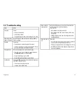


6.2 Troubleshooting
Issue
Action
No power
Check:
• All power connections
• Check relevant fuses
• That power supply is at the correct voltage (12 V or 24 V)
AIS configuration
data is not saved
Switch off all associated multi-function displays (MFDs),
then re-configure
No data
Check that:
• Connections are secure throughout the system
• The VHF aerial lead is securely connected and that you
can send and receive VHF radio information
No vessel data
At the relevant Raymarine multi function display:
• Place the cursor over the targeted vessel and ensure
the
AIS DATA
soft key is not set to
OFF
• Ensure the AIS layer is set to
ON
• Ensure displayed target types are set to
ALL
No AIS data
Check the NMEA output from the multi-function displays to
the AIS500 input, and ensure:
• The wires are correctly connected
• The baud rate is 38400 baud
Status indicator
remains amber
Wait at least 30 minutes to check that a ’Quiet time’ has
not been requested by the local authority
Check that the:
• GPS antenna is properly connected
• GPS antenna has a clear view of the sky, without any
obstructions
• MMSI number has been properly configured (use the
proAIS application)
Status indicator is
red
Check that:
• The VHF antenna is properly connected and in particular
it is not short circuiting to the vessel structure
• That power supply is at the correct voltage (12 V or 24 V)
• The MMSI number has been properly configured (use
the proAIS application)
Diagnostics
41
Summary of Contents for AIS500
Page 1: ...AIS500 Transceiver Installation instructions AUTOMATIC IDENTIFICATION SYSTEM...
Page 2: ......
Page 4: ......
Page 6: ...6...
Page 16: ...16...
Page 34: ...D11649 1 Red Black Power supply Power supply Connect to 12 V dc or 24 V dc 34...
Page 42: ...42...
Page 46: ...46...
Page 47: ......
Page 48: ...www raymarine com...


