


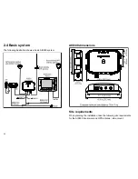


2.4 Basic system
The following illustration shows a basic AIS500 system.
Multifunction
display
CANCEL
OK
RANGE
IN
OUT
PAGE
ACTIV
E
WPTS
MOB
MENU
DATA
AIS500
Transceiver
NMEA0183
(38.4 baud)
NMEA0183
(4.8 baud)
Boat’s existing
VHF antenna
Boat’s existing GPS
antenna (typical)
GPS antenna supplied
with AIS500
Tranceiver
SeaTalk
D
1
1625-1
VHF
radio
SeaTalk
ng
Power in
RS232
0
0
AIS
500
RF
AIS500 dimensions
9.51 in (241.6 mm)
10.76 in (273.3 mm)
7.37 in (187.2 mm)
Compass minimum safe distance: 39 in (1 m)
2.43 in
(61.7 mm)
AIS
500
9.96 in (252.9 mm)
3.46 in
(88 mm)
1.65 in
(41.8 mm)
Site requirements
When planning the installation, take the following site requirements
for the AIS500 transceiver and GPS antenna, into account.
20
Summary of Contents for AIS500
Page 1: ...AIS500 Transceiver Installation instructions AUTOMATIC IDENTIFICATION SYSTEM...
Page 2: ......
Page 4: ......
Page 6: ...6...
Page 16: ...16...
Page 34: ...D11649 1 Red Black Power supply Power supply Connect to 12 V dc or 24 V dc 34...
Page 42: ...42...
Page 46: ...46...
Page 47: ......
Page 48: ...www raymarine com...


