


0049-1200-XXX RM16M – USER’S GUIDE 12/29/2010
Rev. C
Page 20
of
27
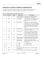
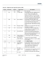
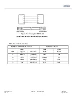
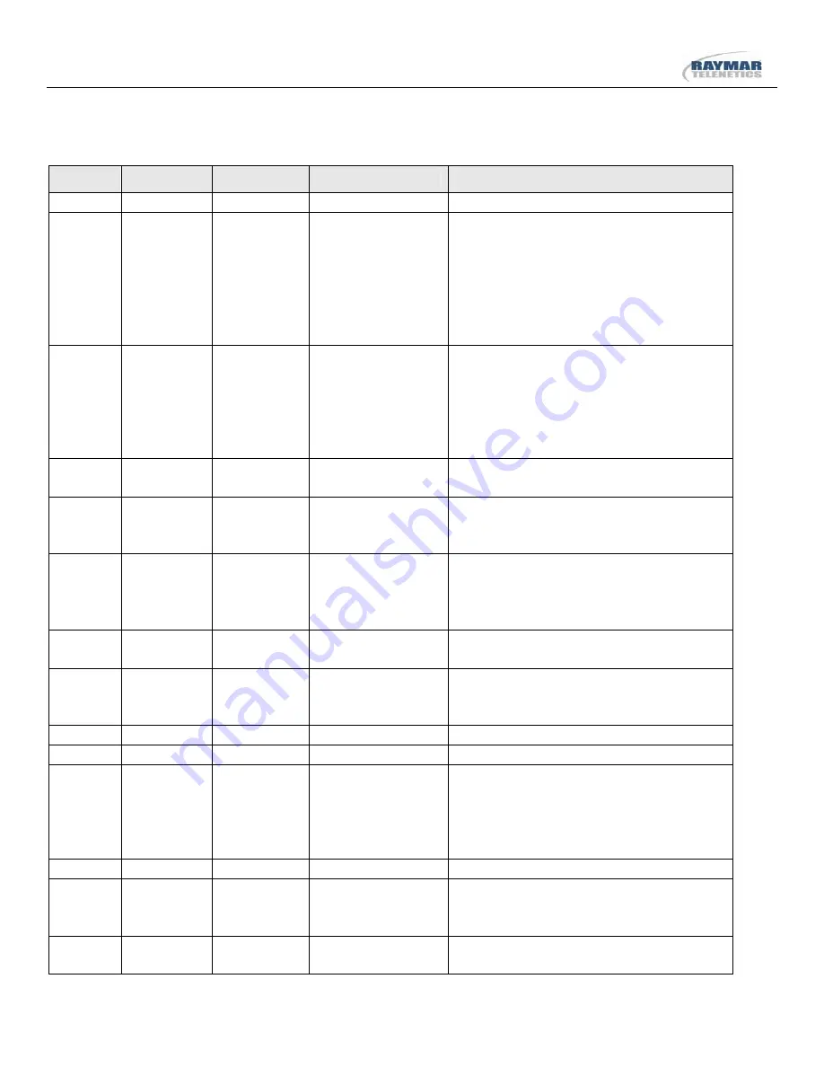
Table B-2. Digital Interface Signal Descriptions (232D)
Pin No. EIA-232C
CCITT
Signal Name
Description
1 101
Shield
No
connection
2
BA
103
Transmit Data
Serial digital data (to be modulated) from
a data terminal or other digital data
source. It must be accompanied by a
transmit clock (pin 15) or by an external
data rate clock (pin 24). Data transitions
should occur on positive-going transitions
at clock. (Synchronous modems only.)
3
BB
104
Received Data
Serial digital data at the output of the
modem receiver. The data is accompanied
by an internal data rate clock (pin 17)
whose positive-going transitions occur on
the data transition. (Synchronous modems
only.)
4
CA
105
Request to Send
A positive level to the modem when data
transmission is desired.
5
CB
106
Clear to Send
A positive level from the modem after
receipt of Request to Send and when the
modem is ready to transmit.
6
CC
107
Data Set Ready
A positive level from the modem when
power is on and it is ready to operate. In
dial-up operation, the modem must be off-
hook to give a high DSR signal.
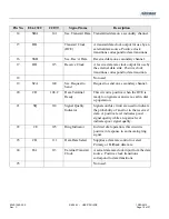
7
AB
102
Signal Ground or
Common Return
Common signal and DC power ground.
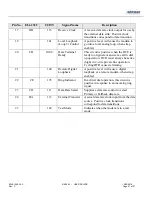
8 CF 109
Received
Line
Signal Detector
A positive level from the modem
indicating the presence of a receive signal
(carrier detect).
9
+12 volts
+12 voltage reference
10
-12 volts
-12 voltage reference
11 CG 110
Signal
Quality
Indicator
Signals on this circuit are used to indicate
the probability of an error in the receive
data. A positive level indicates good
signal quality while a negative level
indicates poor signal quality.
12
Not
used
15 114
Transmit
Clock
(DCE)
A transmit data clock output for use by an
external data source. Positive click
transitions correspond to data transitions.
16
Not
used