background image

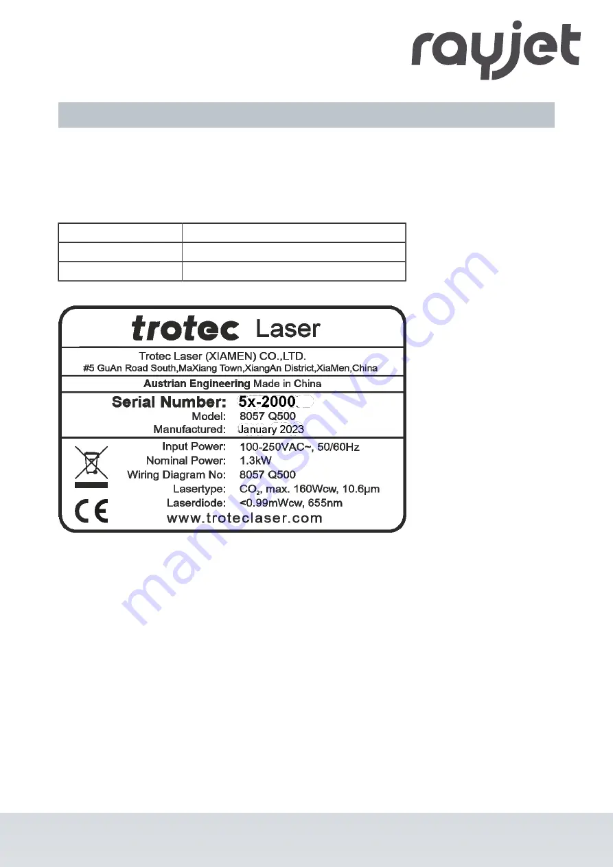
1.5 Type plate

The type plate with the CE mark is located on the rear of the machine.
Enter the serial number, model and year of manufacture into your manual and always refer to them when
contacting us for enquiries, troubleshooting or ordering of replacement parts.

Serial number:
Model:
Year of manufacture:

ENGLISH

ENGLISH

12 / 81

Summary of Contents for R500

Page 1: ...R500 Operation Manual 8057 Operation Manual 8057_4 0_EN 05 2023 ENGLISH...

Page 2: ...aser com Trotec Laser France SAS 33 1 72 62 20 94 techsupport fr troteclaser com Trotec Laser UK 44 0191 4188 110 service uk troteclaser com Trotec Laser Srl 39 02 9475 5447 supporto tecnico troteclas...

Page 3: ...Trotec Laser GmbH Freilingerstra e 99 4614 Marchtrenk Austria General contact to Technical Support Tel 43 7242 239 7000 E mail techsupport troteclaser com www troteclaser com ENGLISH ENGLISH 3 81...

Page 4: ...t prior notice Copyright This documentation with all illustrations is intellectual property of Trotec Laser GmbH The entire documentation is given to the user for personal use only Reproduction transl...

Page 5: ...6 2 3 Areas of responsibility 17 2 3 1 Responsibilities of the operator 17 2 3 2 Responsibilities of the operating personnel 17 2 4 Requirements for operating an service personnel 18 2 5 Machine ident...

Page 6: ...perature and humidity 37 5 4 Required tools for unloading and transport 38 5 5 Place of storage 38 5 6 Transport inspection and reporting of defects 38 5 7 Unpacking the machine 38 5 8 Relocation of t...

Page 7: ...tes 59 8 2 Maintenance schedule 59 8 3 Cleaning 60 8 3 1 Machine 60 8 3 2 Optics in general 61 8 3 3 Lens 61 8 3 4 Mirror 62 8 3 5 Motion system 64 8 3 6 Cleaning drawer 65 8 3 7 Lubricating motion sy...

Page 8: ...ose to the machine This manual describes how to operate the machine properly and safely Be sure to follow the safety instructions given here as well as any local accident prevention regulations and ge...

Page 9: ...to observe the safety instructions leads to risk of serious injury or death Particular care should be taken during maintenance and repair work Warning Laser This symbol warns of potentially dangerous...

Page 10: ...ng from nonobservance of instructions in this manual Nonobservance of the operation maintenance and service instructions described within this manual absolves Trotec Laser GmbH from any liability in c...

Page 11: ...oftware printer driver and operating manual 3 Power cable 4 USB computer connection cable 5 Cleaning kit for optics 6 Lens 7 Focus tool The actual scope of delivery may be different depending on the s...

Page 12: ...he rear of the machine Enter the serial number model and year of manufacture into your manual and always refer to them when contacting us for enquiries troubleshooting or ordering of replacement parts...

Page 13: ...d repaired only by trained personnel familiar with the designated field of use and the dangers of the machine Operate the machine only in technically flawless condition and when it fully complies with...

Page 14: ...affects machine safety 2 1 5 Operating modes Normal operation For normal operation the following conditions must be met Intended use of the machine see chapter Intended use Operation of the machine o...

Page 15: ...ts ISO 13857 2008 Safety of machinery Safety distances to prevent hazard zones being reached by upper and lower limps EN 55011 A1 2016 05 Industrial scientific and medical equipment Radio frequency di...

Page 16: ...d closure reflex and stare into the class 2 laser beam for a time long enough for the eyes to get injured Warning Laser Laser radiation of Class 2 US class II For Class 2 US class II laser is short te...

Page 17: ...machine Authority for the individual activities relating to the application of the machine e g installation operation maintenance and cleaning must be clearly defined and observed so that no unclear...

Page 18: ...he influence of drugs alcohol or reactivity affecting medication when working on or with the machine The personnel must be familiar with using the CO2 fire extinguisher The personnel must be trained i...

Page 19: ...ers If any warning and safety stickers are lost or damaged the user is not able identify risks anymore and there is danger of injury Replace lost or damaged labels immediately Contact your Trotec Lase...

Page 20: ...1 4 7 10 2 5 8 11 3 6 9 ENGLISH ENGLISH 20 81...

Page 21: ...echnical protective measures 2 7 1 Main switch Pressing the main switch on the backside of the machine to disconnect the machine from the mains power supply 2 7 2 Key switch Turning the key switch to...

Page 22: ...r the pilot laser stays active 2 7 5 Acrylic top lid The type of acrylic top lid depends on the laser type It protects the operator from uncontrolled emission of dangerous laser radiation 2 7 6 Side c...

Page 23: ...cooling slots of the cooling system 2 8 2 Gases fumes and dust Depending on the materials being processed and the parameters selected laser processing may generate gases fumes aerosols or dust Dependi...

Page 24: ...s steel brass copper and titanium Take special care with surfaces formed convex and concave Do not leave or put objects on the work surface working area Laser beam reflection The reflecting law is val...

Page 25: ...ies of thorium which may be harmful upon inhalation or swallowing Thermal decomposition Upon thermal decompositions vapors of selenium oxide and zinc oxide are formed Upon inhalation or swallowing the...

Page 26: ...functions In unusual operating conditions open the lid to stop the machining process press the emergency stop button and switch off the machine If necessary disconnect the machine from the main power...

Page 27: ...3 Technical Data The technical data sheet can be found in the appendix of this manual ENGLISH ENGLISH 27 81...

Page 28: ...ug or equivalent The requirements for the exhaust system and recommended Trotec exhaust systems for standard applications depend on the working table installed in the machine Notice Connection has to...

Page 29: ...and table exhaust may also be necessary In this case it is absolute necessary to consult your distributor 3 2 Materials List of material Material EN Material DE Cutting Engraving Marking Metal Alumin...

Page 30: ...PBT Polycarbonate PC Polycarbonat PC Polyethylene PE Polyethylen PE Polyester PES Polyester PES Polyethylene terephthalate PET Polyethylenterephthalat PET Polyimide PI Polyimid PI Polyoxymethylene POM...

Page 31: ...materials Leather and artificial leather that contains chromium VI Carbon fibers Carbon Polyvinyl chloride PVC Polyvinyl butyral PVB Polytetrafluorethylene PTFE Teflon Beryllium oxide Materials contai...

Page 32: ...r a sales partner near you if You are unsure about the processing of a material You have additions for further materials for us or in your opinion a material was not listed We recommend performing a m...

Page 33: ...Acrylic cover 7 Side panel 2 Table 8 Side panel for power supply units 3 Cleaning compartment 9 Rollers 4 Cover for the laser source 10 Adjustable feet 5 Emergency stop button 11 Cover for cleaning op...

Page 34: ...uring processing corresponds to the current power By default this bar graph is always exactly in the middle when the machine is started up on MODIFY Modify means factor 1 The laser power corresponds t...

Page 35: ...work pieces smaller than 100 mm as these remain in a flat position after cutting 4 4 Cleaning drawer The cleaning compartment serves as a dust collector and can be pulled out and cleaned after process...

Page 36: ...r Transport the machine as carefully as possible in order to prevent damage Avoid vibrations When transporting the machine overseas the device must be packaged airtight and protected against corrosion...

Page 37: ...s Transport temperature ambiente temperature 10 C to 40 C 14 F to 104 F Relative humidity Maximum 70 non condensing Avoid high temperature fluctuations Storage conditions Storage temperature ambiente...

Page 38: ...reporting of defects Immediately after receipt inspect the delivery to ensure that it is complete and has not suffered any damage If any transport damage is visible do not accept the delivery or acce...

Page 39: ...h current waste legislation 1 Use a forklift to place the crate in the prepared position 2 First remove the top wooden cover and then the side panels of the crate 3 Remove the aluminum bag for sea fre...

Page 40: ...installation instructions R500 5 8 Relocation of the machine Steps 1 Switch off the machine 2 Disconnect the power cable 3 Remove the exhaust system 4 Reposition the machine e g with auxiliary equipme...

Page 41: ...all over during transport Observe the corresponding safety norms and regulations from the chapters Safety notes and Transport When transporting over long distances use transport boxes including transp...

Page 42: ...exposed to large temperature fluctuations it must first be brought back to room temperature before commissioning Environmental conditions Provide sufficient illumination at the workplace Ensure a dus...

Page 43: ...ription 1 Fuse 6 Connection for external compressor 2 main switch 7 Connection for cooling water 3 Main connection 8 Connection table exhaust system 4 USB connection for PC 9 Connection exhaust system...

Page 44: ...as this may cause damage to the machine Make sure that the mains voltage matches the voltage required by the exhaust system Notice Depending on the laser power and region the main fuses are either co...

Page 45: ...ng system to the laser unit see example 2 Secure the hose connections with cable ties on the machine and on the water cooling system 3 Fill the system with normal water of at least 18 C 64 4 F 4 Check...

Page 46: ...7 Connect the water cooling system cable to the cooling alarm connection ENGLISH ENGLISH 46 81...

Page 47: ...r safety regulations and measures Fulfill and compliance with all laser safety requirements according to chapter 2 If errors or functional deviations should occur during the inspection of the listed p...

Page 48: ...technician Warning Dangerous electrical voltage High voltage can cause serious injury or even death The laser source may only be replaced and installed by trained qualified and authorized personnel Ob...

Page 49: ...cooling 2 Switch on the main power supply using the main switch on the rear of the machine 3 Turn the key switch to the right and hold it against the spring force 4 As soon as the machine starts rele...

Page 50: ...main power Notice By switching off the mains all processing data are lost 7 4 Control panel 7 4 1 Keypad 1 2 3 6 4 5 7 8 9 The control panel refers to the entire unit of the machine control system The...

Page 51: ...table control button Z No function Exhaust button LED On Exhaust active Shift button Second operating level Laser head control button X Y travel distance in X direction travel distance in Y direction...

Page 52: ...n Press this button to stop the current working process Start Pause Repeat button Start Press this button to start a job The job has to be on the plate in RayjetManager Pause Press this button to paus...

Page 53: ...is button to switch the exhaust On Off Notice Only possible for operation with Atmos LED On Exhaust active LED Off Exhaust deactivated After the laser process is completed the exhaust switches off aft...

Page 54: ...me position Laser head control button X Y Laser head moves diagonal to the according direction 7 5 Changing the lens 1 Remove the air assist hose 2 Open the thread on the upper side 3 Open the thread...

Page 55: ...the tube 6 Here Take the 2 0 inch lens out of the socket You can clean or replace the lens 7 Put the tube back on the laser head 8 Insert the lens 9 Tighten the thread again 10 Reconnect the air assi...

Page 56: ...Position of the lens Assembly without lens Assembly with a 2 0 inch lens Assembly with a 4 0 inch lens Notice Make sure that the lens is placed with the convex side facing upwards ENGLISH ENGLISH 56...

Page 57: ...ding the frame from the machine 2 Insert the new table including the frame into the machine Information The slats and the frame are transported individually The slats can be positioned individually in...

Page 58: ...d the material to be processed is decisive for a perfect application result 1 Use the X Y position keys 1 on the control panel to move the processing head over the material to be engraved 2 Place the...

Page 59: ...lectrical voltage Danger of electrical shock Work on electrical fittings may be carried out only by qualified personnel and in strict observance of the safety notes Before any maintenance work takes p...

Page 60: ...m 8 3 Cleaning 8 3 1 Machine 1 Move the working table into a position in which it is easiest for you to clean the surface with a window cleaning agent and paper towels 2 Switch off and disconnect the...

Page 61: ...ng liquid 8 3 3 Lens 1 Remove the air assist hose 2 Now remove the lens and check the surface Here 2 0 inch lensRemove loose particles and dust with a bellows or compressed air ISO 8573 2010 Class 1 3...

Page 62: ...hose 8 3 4 Mirror Cleaning mirror 3 on the working head 1 Unscrew the two screws by hand 2 Loosen the mirror by wiggling it slightly 3 Remove mirror 4 Clean the mirror carefully 5 Mount the mirror ag...

Page 63: ...loose particles and dust with a bellows or compressed air according to ISO 8573 2010 Class 1 Thorough cleaning for heavy dirt 1 Remove the screws from the mirror 2 Remove the mirror Use a cleaning clo...

Page 64: ...le the interior of the machine and the cleaning drawer X axis rail cleaning 1 Clean the entire length of the x axis rail with a cleaning cloth and a cotton swab Use some cleaning foam Trotec or a simi...

Page 65: ...2 strokes with grease gun Recommended lubricants Producer Type HiWin G05 Fuchs RENOLIT LZR2H Kl ber Microlube GL 261 Mobil Mobilus EP2 Recommendation grease gun HiWin GN 80M with lubrication adapter A...

Page 66: ...the x axis to the far left front of the working table Lubrication nipple should be accessible and concentric with hole Press two pump strokes of the grease gun into the lubrication nipple If required...

Page 67: ...ide the working head to the left until the lubrication nipple and hole are concentric Press two pump strokes of the grease gun into the lubrication nipple If required Remove excess grease with paper t...

Page 68: ...the x axis to the far left back of the working table Lubrication nipple should be accessible and concentric with hole Press two pump strokes of the grease gun into the lubrication nipple If required R...

Page 69: ...em Possible cause Remedy Too low engraving depth Imprecise focusing Dirty optics Check focus Clean optics Blurred edges Imprecise focusing Check focus Missing cut lines Zero passes in material databas...

Page 70: ...Increase the correction in JobControl Settings Material Templates Setup Correction No referencing after comissioning Top front or side door not closed Close doors No response upon switching on of the...

Page 71: ...that was sent to RayjetManager and possibly caused a failure e g a CorelDraw file Photoshop file AutoCAD file 5 Click on Open 6 The location to which the successfully created service file was saved a...

Page 72: ...lowing information ready see response form At which working process did the problem occur What you have done so far to correct the problem Serial no see type plate Error code Local Offices Sales Our s...

Page 73: ...al voltage Electric current The machine must be disconnected from the main power supply Notice Always use suitable tools to disassemble the machine Mind the springs Follow chapter Disposal Process 1 R...

Page 74: ...regional directives on electronic and electric waste disposal In case of further questions please ask your supplier In case of disassembly use suitable tools to dismantle the unit into individual par...

Page 75: ...13 Appendix ENGLISH ENGLISH 75 81...

Page 76: ...ems Machine parts checked for shipping damage Machine parts checked against delivery note Setup of the machine discussed Startup of the machine discussed Operation of the machine discussed Maintenance...

Page 77: ...version Layout Software Firmware version Name Country Phone E mail Date Contact details Machine data Does an error message show up on the PC and if so which What happened before the error occurred Thu...

Page 78: ...on Danger areas Warnings Position of the Emergency stop button Personal protective equipment Operating equipment Workflow Setting up Startup and Shutdown Reporting of unexpected working results and ac...

Page 79: ......

Page 80: ...ion thanks to the closed housing secured with in terlocks Features standard and accessories Software Rayjet Manager printer driver Rayjet Manager laser software Compatible with standard graphic and CA...

Page 81: ...er source water cooled Laser power 100 W 120 W Sealed off CO2 RF CeramiCore laser source water cooled Laser power 60 W Water cooling 16 l min Ready for RF upgrade kit Set to upgrade to a sealed off CO...

Reviews: